
Server load balancing apparatus and method using MPLS session

Active Publication Date: 2005-04-14
ELECTRONICS & TELECOMM RES INST
View PDF19 Cites 90 Cited by
  • Summary
  • Abstract
  • Description
  • Claims
  • Application Information

AI Technical Summary

Benefits of technology

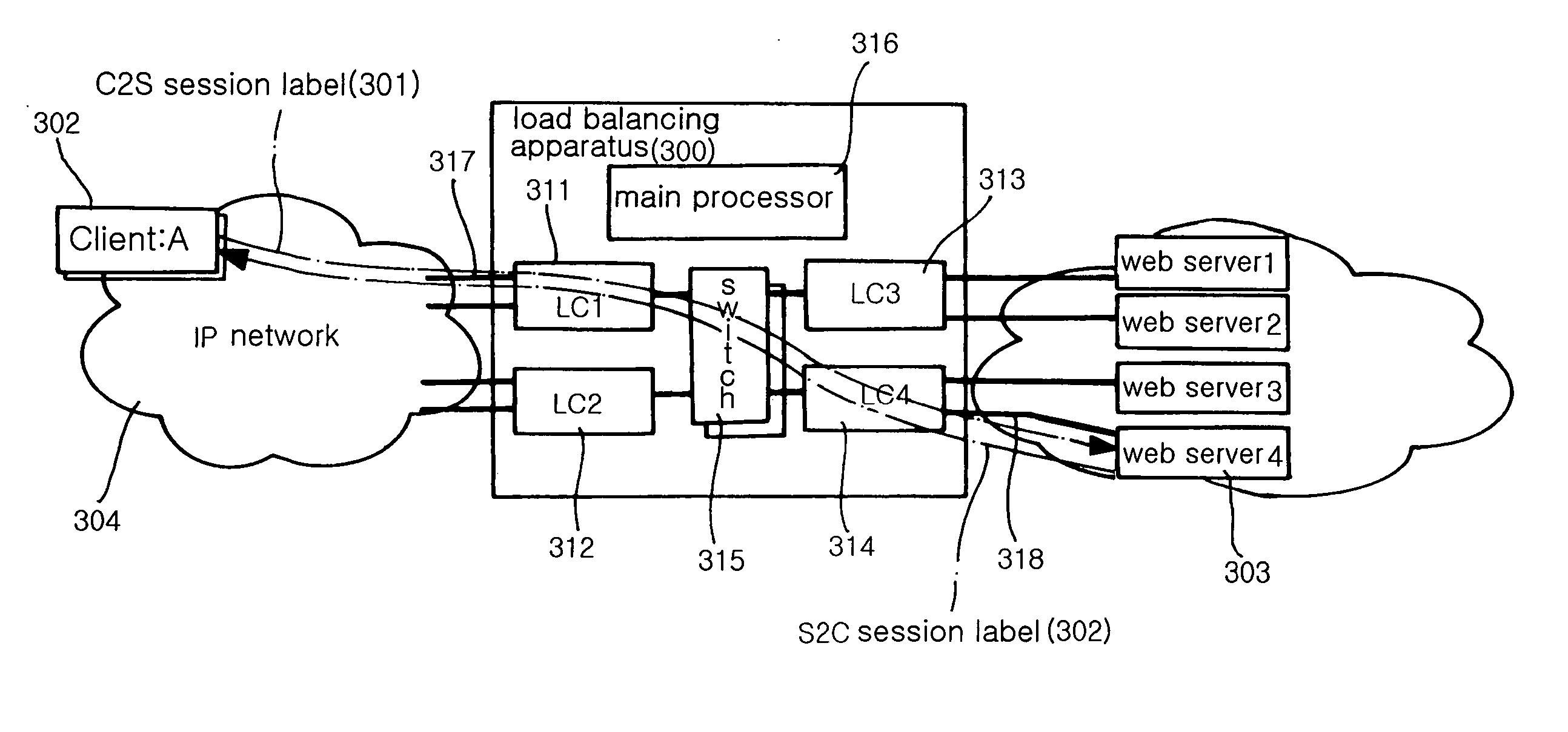
[0011] The present invention provides a server load balancing apparatus and method in a Multi-Protocol Label Switching (MPLS)-based network, which, when a plurality of clients are connected to a plurality of servers through the server load balancing apparatus, attaches the session labels to the headers of packets whose session analysis is completed, and allows the server load balancing apparatus to determine a server for connection using only session label information, so that the load balancing apparatus does not perform a complicated process of analyzing all the packets and a function of converting the IP addresses of actual servers into the virtual IP address of the load balancing apparatus is excluded, thus considerably simplifying the process of the load balancing apparatus and, therefore, improving the performance of the load balancing apparatus.

Problems solved by technology

However, the conventional load balancing apparatus requires additional complicated software processes of comparing and analyzing the header information of all packets ranging from a second layer to a seventh layer, thus reducing the performance of the loading balancing apparatus.
However, the conventional load balancing apparatus is problematic in that it should perform additional processes of intercepting all the packets and changing destination or source IP addresses information from the IP addresses of the actual servers to the virtual IP address of the server load balancing apparatus.
However, the preceding patents still have the problems of the prior art, and do not reduce processing overhead caused while analyzing the header information of all the packets for the load balancing.

Method used


Image

  • Server load balancing apparatus and method using MPLS session
  • Server load balancing apparatus and method using MPLS session
  • Server load balancing apparatus and method using MPLS session

Examples


Embodiment Construction

[0023] Reference now should be made to the drawings, in which the same reference numerals are used throughout the different drawings to designate the same or similar components.

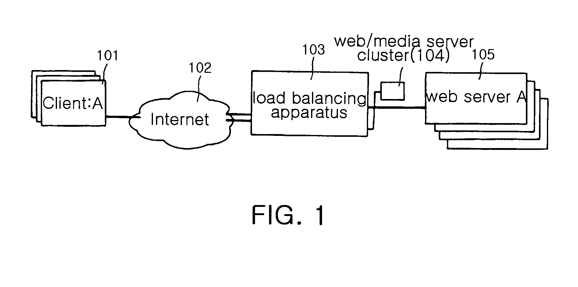
[0024]FIG. 1 is a view showing an example of the configuration of a service network to which a server load balancing apparatus 103 according to the present invention is applied. As shown in FIG. 1, in the configuration of the service network for providing a server connection service to which the present invention is applied, a plurality of clients 101 are connected to a server farm 105 composed of a plurality of servers through the Internet 102, and the server load balancing apparatus 103 according to the present invention is located in front of the server farm 105, analyzes requests from the clients 101 and distributes the requests among the servers 105. The reference numeral 104 designates a web / media server cluster.

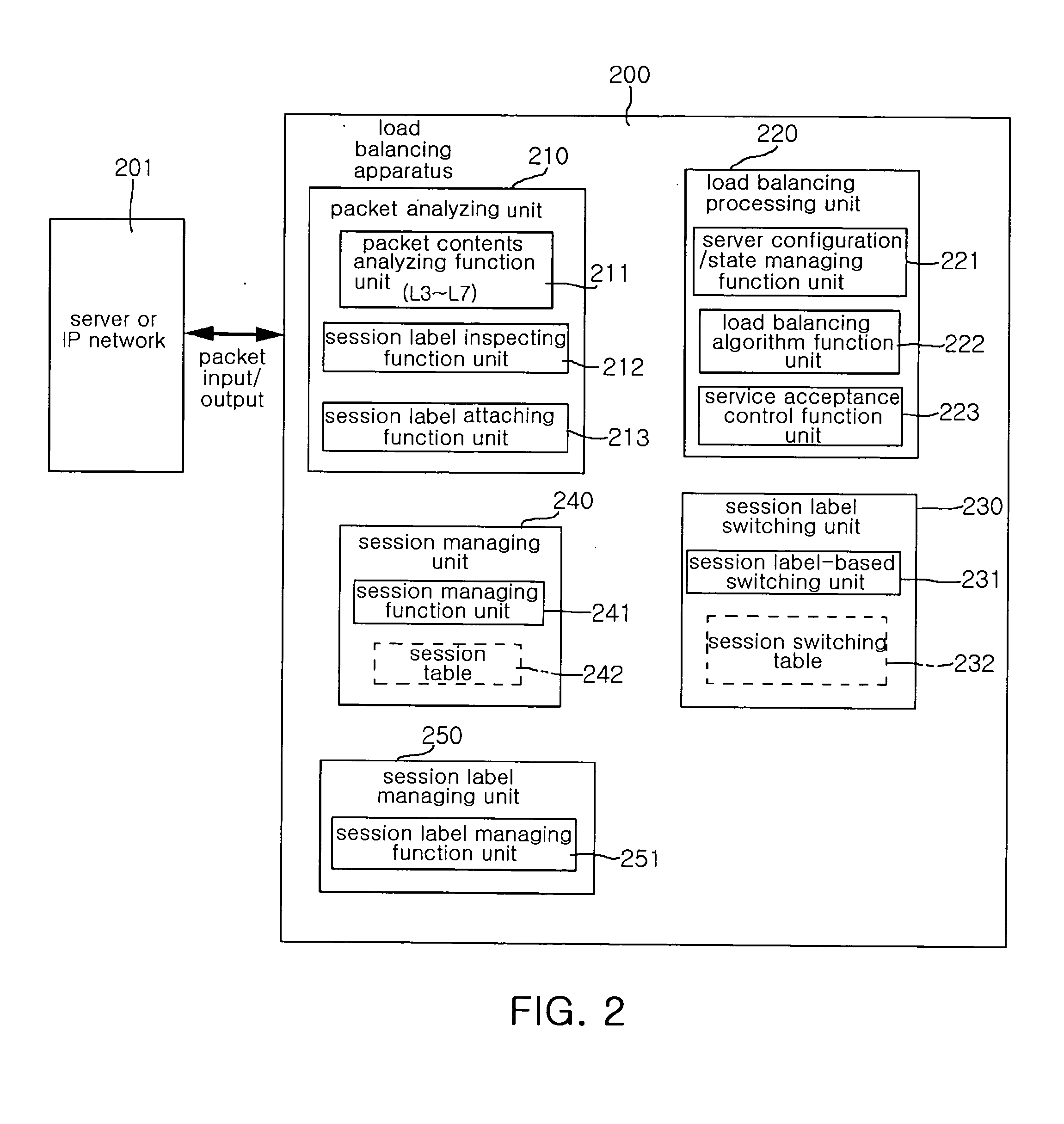
[0025]FIG. 2 is a function block diagram showing a server load balancing apparatus 200 acc...


PUM


Abstract

The present invention provides a server load balancing apparatus using MPLS session labels. The server load balancing apparatus includes a packet analyzing unit, a load balancing processing unit, a session label switching unit, a session managing unit, and a session label managing unit. The packet analyzing unit inspects whether a session label has been attached to a received packet, analyzes header information of the received packet to learn session information, and attaches a session label to a header of the received packet. The load balancing processing unit assigns a server to a session of the received packet without the session label attached. The session label switching unit hardware-switches the received packet with the session label attached using only the session label information. The session managing unit manages and maintains relevant information and states of sessions. The session label managing unit manages the session label.

Description

BACKGROUND OF THE INVENTION [0001] 1. Field of the Invention [0002] The present invention relates generally to a load balancing apparatus and method, and more particularly to a server load balancing apparatus and method using multi-protocol label switching session labels, which, when packets are transmitted from a plurality of clients to a plurality of servers through the Internet, distributes loads among the servers by attaching the multi-protocol label switching session labels to the headers of the packets in front of the servers and determining a server for connection using session label information. [0003] 2. Description of the Prior Art [0004] As various Internet-based multimedia services and e-commerce have been popularized, a plurality of web servers constitutes a server farm having a cluster form, and a server load balancing apparatus is generally located in front of the server farm. [0005] The server load balancing apparatus located in front of the servers to balance servic...

Claims


Application Information

Patent Timeline
IPC IPC(8): G06F15/173H04L12/28H04L29/06H04L29/08
CPCH04L67/1008H04L67/1002H04L67/1023H04L67/1017H04L69/22H04L67/1001H04L12/28
Inventor YANG, SUN HEEYOON, HYEON SIKPARK, PYUNG KOOYOON, HO SUN
Owner ELECTRONICS & TELECOMM RES INST
Learn More