Method for heating a glow plug for a diesel engine

a technology for diesel engines and glow plugs, which is applied in the direction of engine starters, lighting and heating apparatus, electric control, etc., can solve the problems of excess temperature damage and the need for a long time for the glow plug to reach the desired temperature, so as to avoid overheating the glow plug

Active Publication Date: 2005-04-21
BERU AG DE
View PDF14 Cites 32 Cited by
  • Summary
  • Abstract
  • Description
  • Claims
  • Application Information

AI Technical Summary

Benefits of technology

[0008] A primary object of the present invention is thus to provide a method of the type specified initially which avoids overheatin

Problems solved by technology

If an already hot glow plug is heated, it can be damaged by excess temperature.
However, this has the disadvantage that this fo

Method used


Image

  • Method for heating a glow plug for a diesel engine
  • Method for heating a glow plug for a diesel engine

Examples


Embodiment Construction

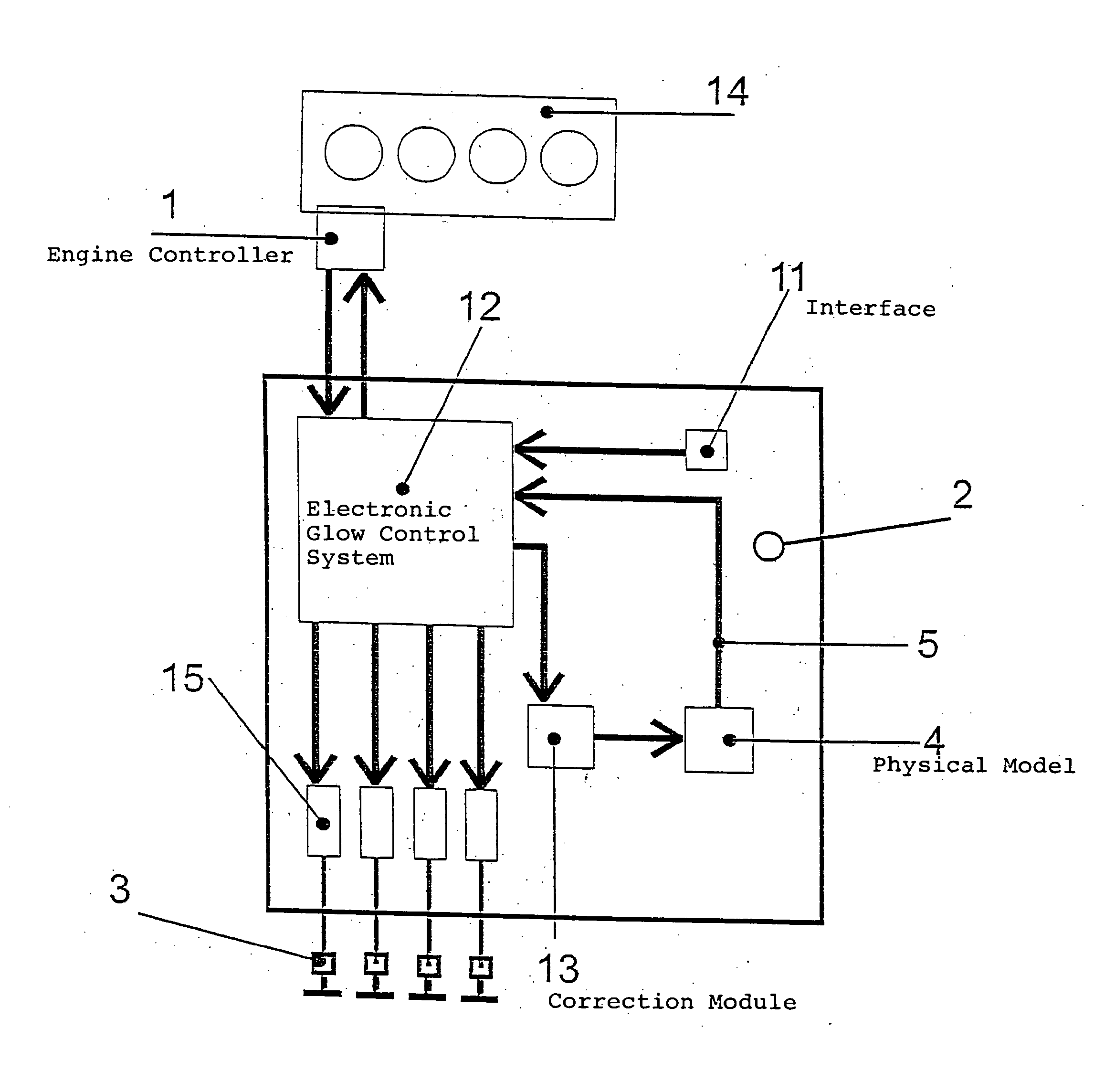
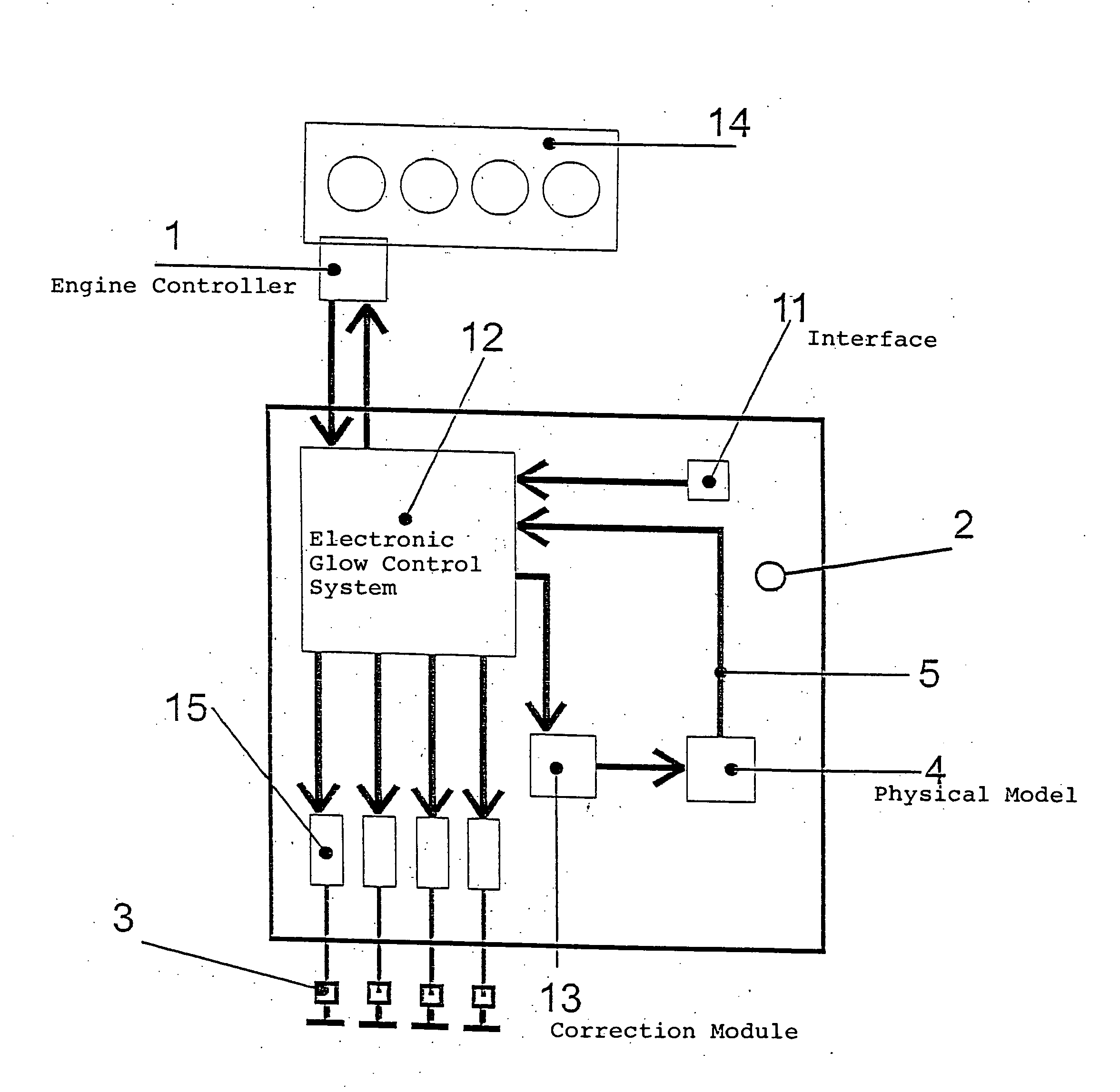
[0016] The control device shown in the drawing comprises an engine controller 1 and a glow controller 2 at which a glow request from the engine controller 1 is applied via a suitable interface. The glow controller 2 interprets the glow request and passes current through the glow plug 3 accordingly.

[0017] A physical model 4 of the glow plug is provided in the glow controller 2 which is controlled parallel to the glow plug 3 so that the thermal state of the glow plug 3 is depicted by this physical model 4. The physical model 4 is designed so that at least when the engine is not running, i.e., without gas change or fuelling, it accurately depicts the temperature of the heating rod tip of a conventional glow plug. This applies both to the heating up and to the cooling down of the glow plug.

[0018] The resistance of a suitably dimensioned PTC or NTC element within the physical model 4, for example, can serve as a measure for the thermal state of the glow plug. Instead of this, an electr...


PUM


Abstract

A method for heating a glow plug for a diesel engine to its desired temperature by supplying power to the glow plug in a controlled fashion. During a certain time interval after termination of a previous glow process, a mathematical model is used to determine the values for the supply of power to the glow plug, which includes the values of the actual thermal state of the glow plug, the time elapsed since the end of the previous glow process and the parameters of the diesel engine relevant for a glow process.

Description

BACKGROUND OF THE INVENTION [0001] 1. Field of the Invention [0002] The invention relates to a method for heating a glow plug for a diesel engine to a desired or set temperature, by passing current through the glow plug in a controlled manner. [0003] 2. Description of Related Art [0004] A method of the above noted type is used to bring a glow plug of a diesel engine up to the set temperature at which the engine can be started. [0005] A method for controlling the heating-up of a glow plug for a diesel engine is known from MTZ 10 / 2000 “The electronically controlled ISS glow system for diesel engines”, in which the glow command or the glow request is given after initialization of the engine control system has been completed, after the temperature of the engine elements has been determined via the engine control system and communication has then been successfully set up between the engine control system and the glow controller. [0006] In order to control the heating-up of a glow plug of...

Claims


Application Information

Patent Timeline
IPC IPC(8): F02D41/06F02N99/00F02N19/04F02P17/12F02P19/02F23Q7/00
CPCF02D41/064F02D2041/1423F02P19/025F02P17/12F02P19/023F02D2041/1433F02P19/02
Inventor TOEDTER, OLAFSCHMITZ, HEINZ-GEORGBLEIL, ANDREASSTOECKLE, JOERGHOUBEN, HANS
Owner BERU AG DE
Why Eureka
Try Eureka