Partition plate for intake port, intake port molding sand core and cylinder head

a technology for intake ports and cylinder heads, which is applied in the direction of foundry moulding apparatus, combustion air/fuel air treatment, foundry patterns, etc., can solve the problems of unintentional force applied, positional shift or drift relative, and the partition plate cannot exhibit the desired function, so as to improve the positional shift of the partition plate and improve the quality of the cast produ

Inactive Publication Date: 2005-04-21
NISSAN MOTOR CO LTD +1
View PDF3 Cites 13 Cited by
  • Summary
  • Abstract
  • Description
  • Claims
  • Application Information

AI Technical Summary

Benefits of technology

[0006] The present invention is provided in view of the above-described circumstances. According to the present invention, quality of a cast product is improved by preventing the positional shift of the partition plate relative to the intake port molding sand core, thereby largely improving the positional shift of the partition plate relative to the intake port.

Problems solved by technology

However, in the above-described method, the partition plate is held to the intake port molding sand core by a weak interactive force.
Therefore, while the core is handled, an unintentional force is applied, and a positional shift or drift relative to the core is possibly caused by the unintentional external force.
The generation of the positional shift of the partition plate relative to the core, further involves the positional shift of the partition plate relative to the intake port at the time of cast-molding of the cylinder head, thereby posing a problem that the partition plate can not exhibit desired function.

Method used


Image

  • Partition plate for intake port, intake port molding sand core and cylinder head
  • Partition plate for intake port, intake port molding sand core and cylinder head
  • Partition plate for intake port, intake port molding sand core and cylinder head

Examples


first embodiment

[0026] A cylinder head 10 having a partition plate 100 for an intake port 14 will be explained. It is noted that in the explanation given hereafter, the partition plate 100 for the intake port 14 is also referred to as “tumble plate”100.

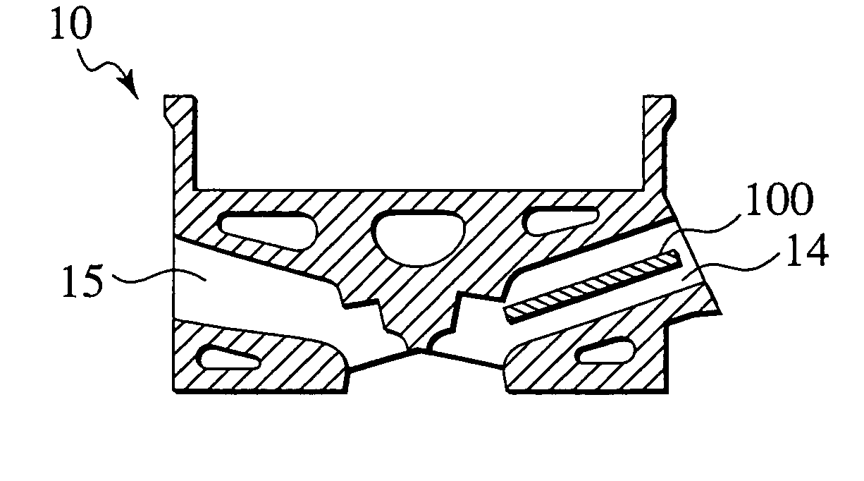
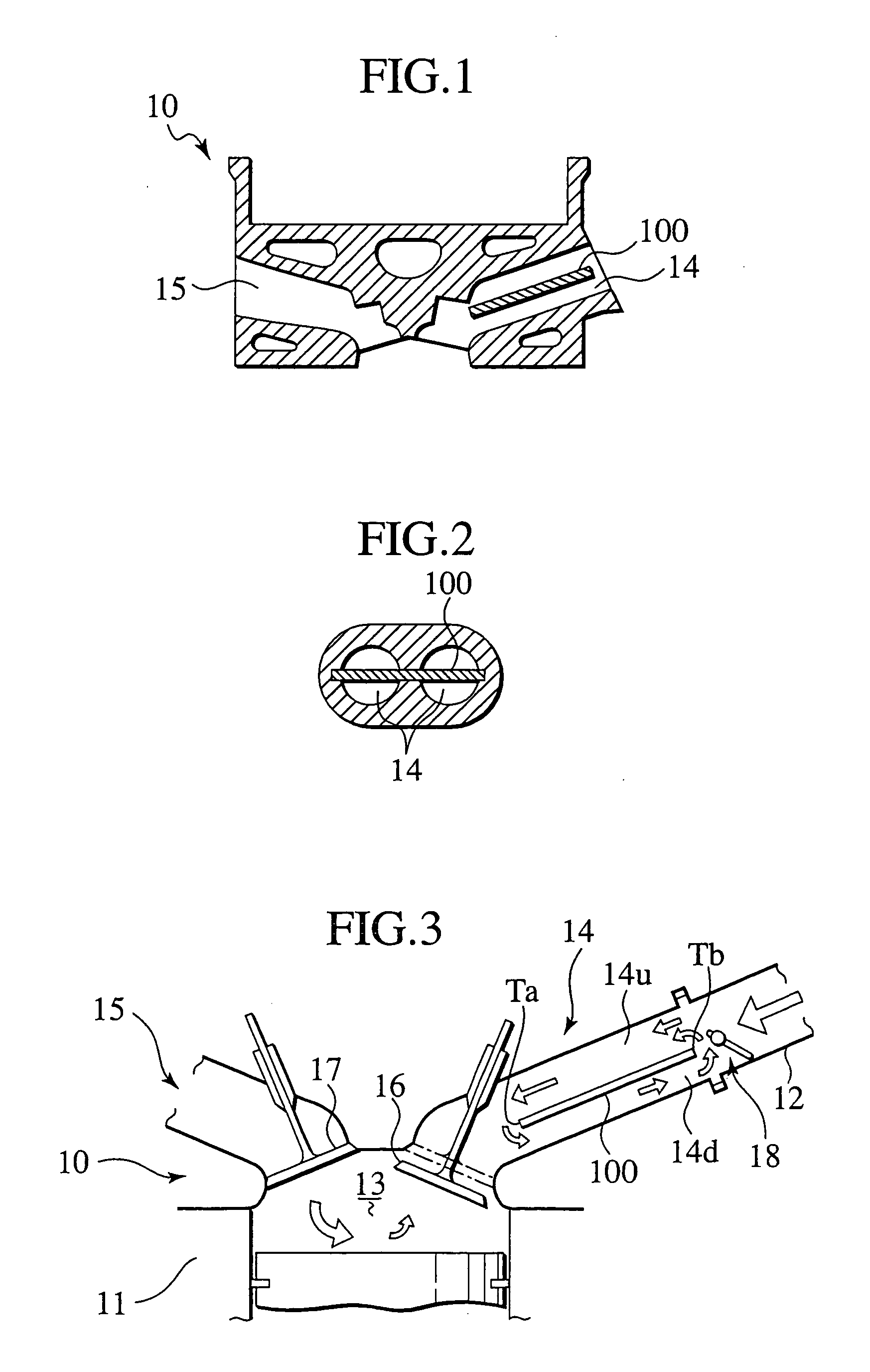
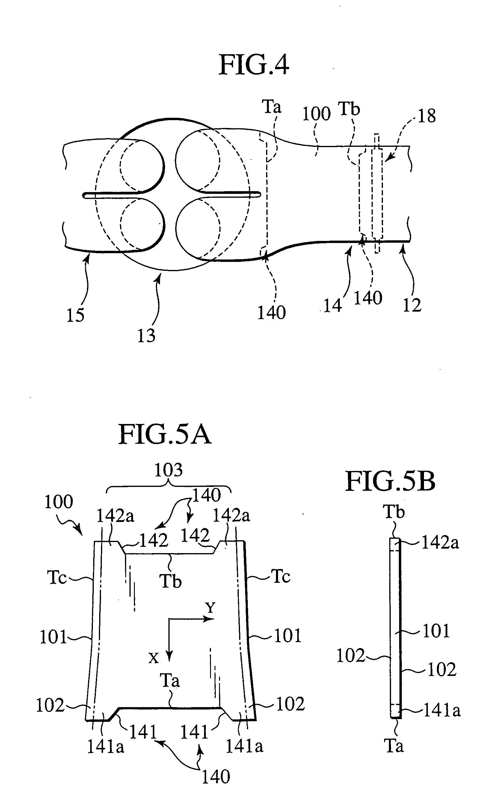
[0027]FIG. 1 is a schematic sectional view illustrating the cylinder head 10 of an engine, FIG. 2 is a cross sectional view of an intake port 14 perpendicular to the primary axis thereof, FIG. 3 is a schematic view illustrating an air current in the cylinder head 10, and FIG. 4 is a schematic plan view of FIG. 3.

[0028] When FIG. 1 and FIG. 3 are referred to, the cylinder head 10 is provided in an upper part of a cylinder block 11, and has an intake port 14 for introducing intake flow comprising air and fuel gas from an intake manifold 12 into a cylinder bore 13, and an exhaust port 15 for discharging exhaust gas produced after combusted in a cylinder bore 13. It is noted that the engine as shown in the figure has one cylinder and four valves, and i...

second embodiment

[0065]FIG. 12A and FIG. 12B are a plan view illustrating a tumble plate 100d according to a second embodiment, and a plan view illustrating a port core 200d in which the tumble plate 100d is previously placed. The tumble plates 100d and 10e of the second embodiment are different from those of the first embodiment in that the step portions 143 and 144 serving as a shift preventing portion 140 are positioned in the center portion of the cylinder side end portion Ta.

[0066] The step portions serving as the shift preventing portion are not limited to a case where they are arranged closer to the both side edge parts Tc of the cylinder side end portion Ta and / or the intake side end portion Tb, but may be arranged in substantially the center of the cylinder side end portion Ta and / or the intake side end portion Tb.

[0067] In this embodiment, as shown in FIGS. 12A and 12B, the step portions 143 are positioned in the center portion of the cylinder side end portion Ta, and provided with one p...

third embodiment

[0068]FIG. 13A and FIG. 13B are a plan view illustrating a tumble plate 10e according to a third embodiment, and a plan view illustrating a port core 200e in which the tumble plate 10e is previously placed.

[0069] The tumble plates 100d and 100e of the third embodiment are different from those of the first embodiment in that the step portions 143 and 144 as the shift preventing portion 140 are positioned in the center portion of the cylinder side end portion Ta.

[0070] In addition, in the third embodiment, as shown in FIG. 13A and FIG. 13B, the step portion 144 is formed by having one recess portion 144a positioned in the center portion of the cylinder side end portion Ta so as to be recessed toward the upper flow side.

[0071] In either case of the second embodiment or the third embodiment, the step portions 143 and 144 of the tumble plates 100d and 10e are arranged by being positioned in the core sand 210 that forms port cores 200d and 200e. Even if the step portions 143 and 144 ar...


PUM

PropertyMeasurementUnit
thicknessaaaaaaaaaa
timeaaaaaaaaaa
interactive forceaaaaaaaaaa

Abstract

A partition plate (tumble plate) for an intake port is previously placed in an intake port molding sand core (port core) for forming an intake port of a cylinder head, and cast-in as the cylinder head is cast-molded, to partition the intake port into a plurality of ports. The partition plate is provided with shift preventing portion that prevent positional shift relative to the intake port molding sand core.

Description

BACKGROUND OF THE INVENTION [0001] The present invention relates to a partition plate for an intake port, an intake port molding sand core and a cylinder head. [0002] A cylinder of an internal combustion engine of recent years includes a cylinder having a partition plate, which is also called a tumbling plate. By controlling a flow control valve arranged in an intake side end portion of the intake port, intake air introduced into a cylinder bore from the intake port is made to flow in an eccentric manner by the partition plate, thereby enhancing a tumble flow (vertical swirl) generated in the cylinder bore, so that a fuel consumption is improved. [0003] It is noted that in the partition plate, the side into which the intake air such as air and fuel gas flows, is referred to as “intake side”, and the opposite side, that is, the cylinder bore side is referred to as “cylinder side” in this specification. SUMMARY OF THE INVENTION [0004] At the time of cast-molding of the cylinder head, ...

Claims


Application Information

Patent Timeline
Patent Type & Authority Applications(United States)
IPC IPC(8): B22C9/10B22D19/00B22D19/08F02B31/04F02B31/06F02B31/08F02D9/10F02F1/24F02F1/42F02M35/10F02M35/108
CPCB22C9/10Y10T29/49231F02B31/04F02B31/06F02B31/08F02B31/085F02B2275/48F02D9/10F02F1/4242F02F2200/06F02M35/10085F02M35/10216F02M35/10262F02M35/10327F02M35/10347F02M35/1085Y02T10/125Y02T10/146B22D19/00Y02T10/12B22D19/08
Inventor YAGETA, KENJINAKABAYASHI, SHIGEKI
Owner NISSAN MOTOR CO LTD
Why Eureka
Try Eureka