
Method and apparatus for generation of electrical power from solar energy

a technology of solar energy and electrical power, applied in the field of solar energy generation methods and systems, can solve the problems of high cost, low efficiency, and low cost of photovoltaic solar cells, and achieve the effects of reducing silicon usage, reducing the overall cost of solar based electrical power generation, and improving efficiency

Inactive Publication Date: 2005-04-21
STEWART ROGER G
View PDF5 Cites 231 Cited by
  • Summary
  • Abstract
  • Description
  • Claims
  • Application Information

AI Technical Summary

Benefits of technology

[0011] In a first preferred embodiment of the present invention, a unique planar concentration panels reduces silicon usage to approximately less than 1% of what is required today and supports a reduction in the overall cost of solar based electrical power generation to about 12¢ / KWhr. Availability of these new photovoltaic electric power generators, will support an acceleration of a transition to renewable solar energy, and a general adoption of solar based electrical power generation by about 10 years.
[0012] The method of the first preferred embodiment of the present invention, or silicon sunflower, employs a novel solar concentrator that permits generation of roughly 400 times as much power from a silicon wafer as could be achieved with a direct-sunlight solar panel. Since the silicon is used more efficiently, more sophisticated silicon photovoltaic cells can be used to double the sunlight-to-electricity conversion efficiencies from roughly 12% for direct-sunlight cells to over 25%. The silicon sunflower thus captures some of the benefits of solar concentrators, yet the silicon sunflower may be scaled and implemented, in certain alternate preferred embodiments of the present invention, in a way that overcomes the thermal and mechanical drawbacks of conventional solar concentrator devices.

Problems solved by technology

The current high cost of photovoltaic solar cells is a significant barrier to widespread deployment of renewable energy sources.
Current solar cell generating systems are barely competitive with even the most expensive peak power generation rates of about 20¢ / KWhr.
These high costs are driven mainly by the requirement for huge quantities of polysilicon, amorphous silicon, or single-crystal silicon used in their construction.
The requirement for such large quantities of processed silicon wafers also raises significant environmental issues.

Method used


Image

  • Method and apparatus for generation of electrical power from solar energy
  • Method and apparatus for generation of electrical power from solar energy
  • Method and apparatus for generation of electrical power from solar energy

Examples


Embodiment Construction

[0054] Reference will now be made in detail to the present preferred embodiments of the present invention as illustrated in the accompanying drawings.

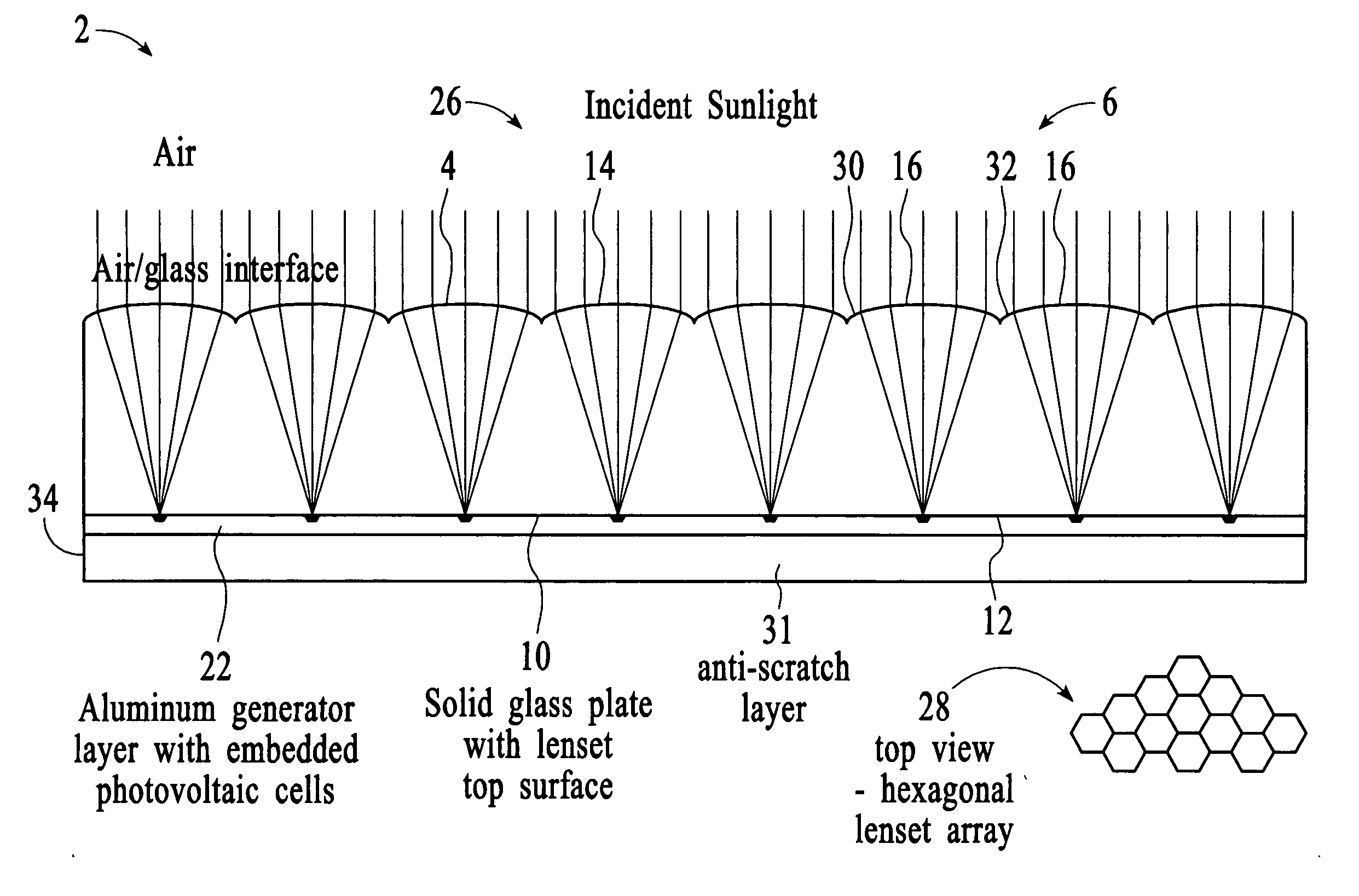
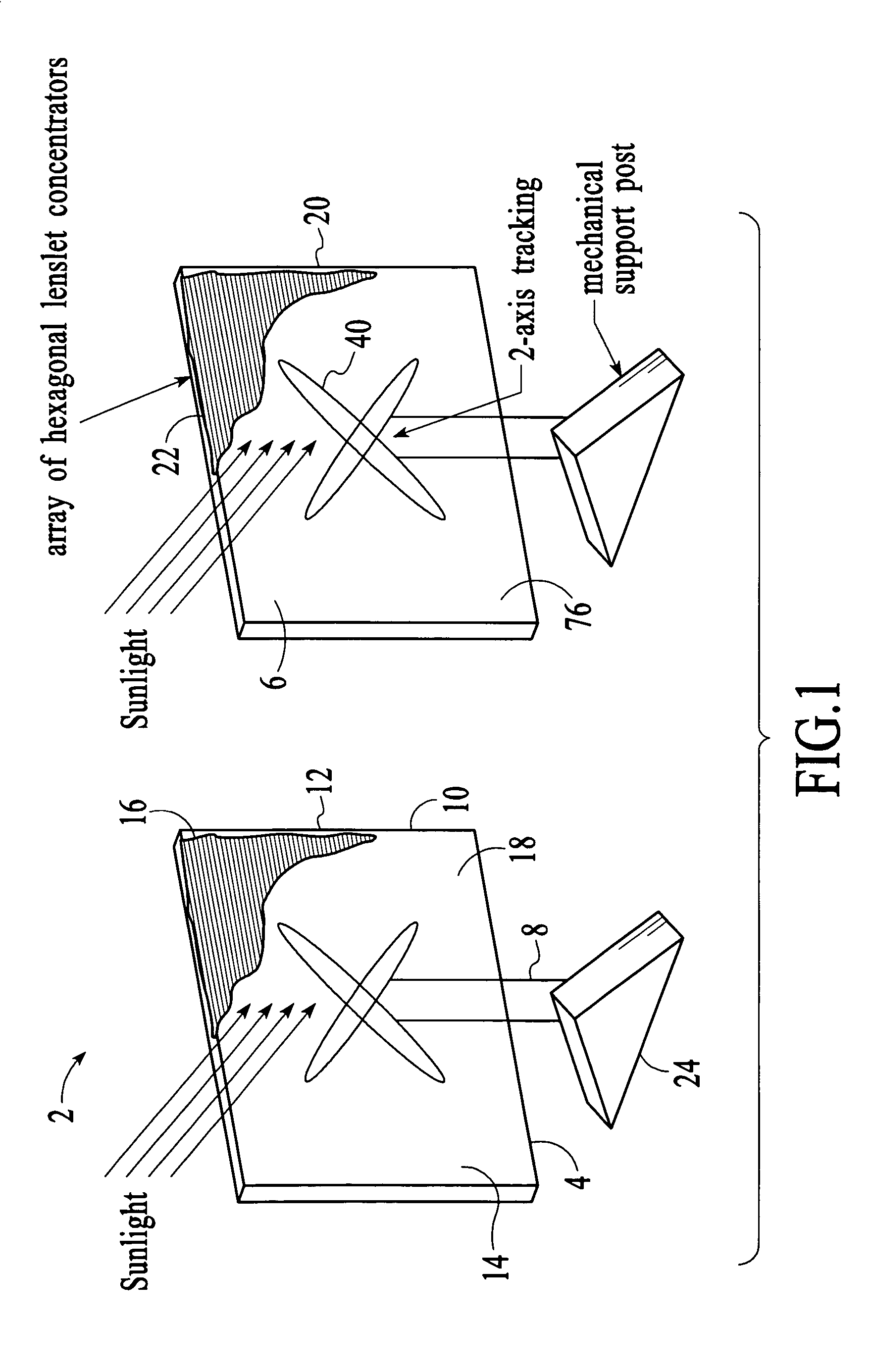
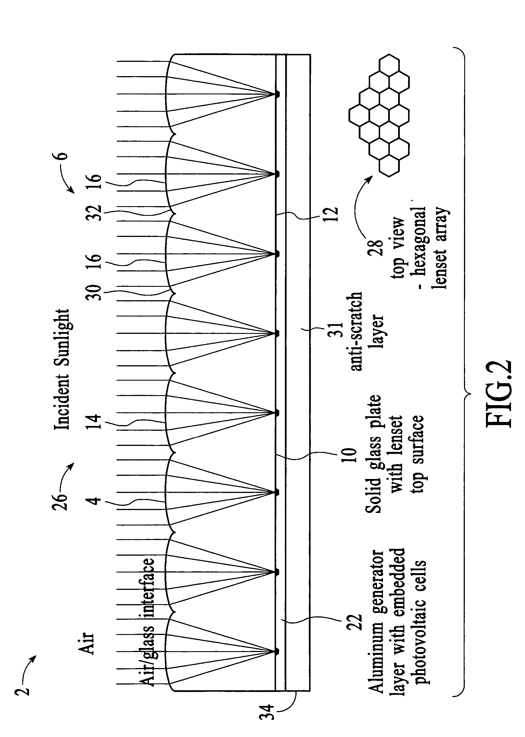
[0055] Referring now generally to the Figures and particularly to FIG. 1, FIG. 1 presents a first preferred embodiment of the present invention 2, or silicon sunflower 2, includes a miniaturized concentrator array plate 4 that may be fabricated as 0.5×0.5 meter (20 inch square) glass plates 6 on a 2-axis steering mount 8. Each plate 6 is about 8-9 mm thick with a flat surface 10 on the back 12 and a pressed-glass front surface 14 forming a multiplicity of small hexagonally shaped lenses or lenslets 16.

[0056] Both the silicon photovoltaic devices 18, or photovoltaic cells 18, and the control electronics 20 are integrated into an electrical power generation layer 22 that is laminated onto the back surface 12 of the glass plate 6. Signals and power from this generation layer 22 are also used to drive tiny motors 24 in the 2-axis mount 8...


PUM


Abstract

A method of providing an apparatus and system comprising a complete smart solar electrical power generator system integrated into the form of a thin flat glass plate. The novel elements include: a micro-scale optical array, a new type of miniaturized photovoltaic cell, an inside-the-lens concentrator design, integral heat sinking and mechanical support, a sealed solid-state design with no air gaps and a new process for building it, combined reflective / refractive light concentration around the photovoltaic cell, variable solar concentration ratios, and a new integrated structure for interconnecting the system together.

Description

CROSS REFERENCE TO RELATED APPLICATIONS [0001] This application is related to and claims priority from U.S. Provisional Patent Application No. 60 / 456,202, entitled “Silicon Sunflower”, filed on Mar. 19, 2003, and which is incorporated by reference in its entirety herein.BACKGROUND OF THE PRESENT INVENTION [0002] 1. Field of Invention [0003] The present invention relates to generating electrical power. More particularly, the present invention relates to methods and systems for generating electrical power from solar energy. [0004] 2. Background of the Invention [0005] The current high cost of photovoltaic solar cells is a significant barrier to widespread deployment of renewable energy sources. Currently the annualized cost of current photovoltaic solar cell systems is about 25¢ / KWhr vs. only 3-4¢ / KWhr for modern gas or coal burning baseline power generating plants. Current solar cell generating systems are barely competitive with even the most expensive peak power generation rates of...

Claims


Application Information

Patent Timeline
IPC IPC(8): H01L31/00H01L31/0352H01L31/052H01L31/18
CPCH01L31/035281H01L31/1804H01L31/0543Y02E10/547Y02E10/52Y02P70/50
Inventor STEWART, ROGER G.
Owner STEWART ROGER G
Learn More