Micro-channel long molecule manipulation system

Inactive Publication Date: 2005-04-21
WISCONSIN ALUMNI RES FOUND
View PDF29 Cites 36 Cited by
  • Summary
  • Abstract
  • Description
  • Claims
  • Application Information

AI Technical Summary

Benefits of technology

[0014] The present invention provides a method for straightening, aligning, separating, and/or sorting polymeric molecules using well-controlled laminar flow in a micro-channel. The molecules may be fixed to a substrate after straightening, aligning, separating and/or sorting, or may be

Problems solved by technology

These latter techniques do not produce uniformly elongated molecules and are often difficult to

Method used


Image

  • Micro-channel long molecule manipulation system
  • Micro-channel long molecule manipulation system
  • Micro-channel long molecule manipulation system

Examples


Embodiment Construction

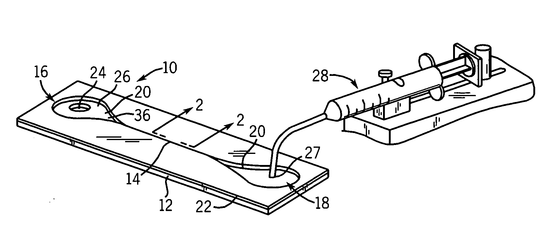
[0057] Referring now to FIG. 1, the apparatus 10 of the present invention provides a generally planar channel plate 12 into which a longitudinally extending micro-channel 14 is formed, flanked by a staging reservoir 16 and a collecting reservoir 18 positioned at longitudinal ends of the channel plate 12.

[0058] Junctions between the longitudinal ends of the micro-channel 14 and staging reservoir 16 and collecting reservoir 18 are tapered to create funnel sections with narrow ends attached to the micro-channel 14 and wide ends attached to one of the staging reservoir 16 or collecting reservoir 18. The funnel sections 20 provide a smooth transition of fluid from the staging reservoir 16 through the micro-channel 14 to the collecting reservoir 18 thereby promoting laminar flow within the micro-channel 14 and reducing breakage of polymeric molecules as will be described.

[0059] One common wall of the staging reservoir 16, the collecting reservoir 18, and the micro-channel 14 is provided...


PUM

PropertyMeasurementUnit
Widthaaaaaaaaaa
Frequencyaaaaaaaaaa
Timeaaaaaaaaaa

Abstract

Laminar flow of a carrier liquid and polymeric molecules through micro-channels is used to straighten, align, separate, and/or sort the polymeric molecules. The polymeric molecules may be analyzed and/or manipulated in the carrier liquid or attached to a wall of the micro-channel for subsequent treatment and analysis. Micro-channels can be manufactured using an elastic molding material. One micro-channel embodiment provides fluid flow using a standard laboratory centrifuge.

Description

CROSS-REFERENCE TO RELATED APPLICATIONS [0001] This application is a continuation in part of U.S. application ______ being a conversion of U.S. Provisional application 60 / 419,884 filed Oct. 18, 2002, hereby incorporated by reference, [0002] which is a continuation in part of U.S. Pat. No. 6,610,256 filed Sep. 24, 2001, [0003] which is a continuation of U.S. Pat. No. 6,294,136, filed May 13, 1997, [0004] which is a continuation of U.S. Pat. No. 5,720,928, filed Apr. 3, 1995, all hereby incorporated by reference. [0005] Alternatively, this application claims the benefit of U.S. Provisional application 60 / 419,884-filed Oct. 18, 2002, hereby-incorporated by reference.STATEMENT REGARDING FEDERALLY SPONSORED RESEARCH OR DEVELOPMENT [0006] This invention was made with United States government support awarded by the following agencies: DOE DE-FGO2-99ER62830 and NIH HG00225. [0007] The United States has certain rights in this invention.BACKGROUND OF THE INVENTION [0008] The present invention...

Claims


Application Information

Patent Timeline
IPC IPC(8): B01L3/00G01N15/02
CPCB01L3/502761B01L2200/0663B01L2300/0816B01L2400/0409G01N2015/0288B01L2400/0478B01L2400/0481G01N15/0255B01L2400/0415
Inventor SCHWARTZ, DAVID CHARLESDIMALANTA, EILEEN T.DE PABLO, JUAN J.
Owner WISCONSIN ALUMNI RES FOUND
Why Eureka
Try Eureka