Image sensing apparatus and image sensor for use in image sensing apparatus

a technology image sensor, which is applied in the field of image sensing apparatus, can solve the problems of deteriorating image quality, fixed pattern noise, and the possibility of electric charge generation, and achieve the effect of accurate evaluation

Inactive Publication Date: 2005-04-21
KONICA MINOLTA CAMERA
View PDF3 Cites 87 Cited by
  • Summary
  • Abstract
  • Description
  • Claims
  • Application Information

AI Technical Summary

Benefits of technology

[0011] It is an object of the present invention to provide an image sensing apparatus capable of measuring a dark current or a noise such as a fixed pattern noise without generating a photographing suspended time, and capable of performing image processing in conformity to the operative status of an image sensor by accurately evaluating the quantity of the dark current or the noise of the image sensor and by feeding back data representing the quantity to an image processing section.

Problems solved by technology

In the image sensor, there is likelihood that electric charges may be generated despite the fact that light is not actually received.
If image formation is conducted based on image data containing a dark current component, an object image containing a detection error corresponding to the dark current component may be reproduced, thereby deteriorating quality of the formed image.
The aforementioned technique has drawbacks that a fixed pattern noise and a variation in temperature characteristics of a dark current are generated with respect to each pixel.
In this arrangement, the camera is brought to a photographing suspended state during the shutter-closing time, thereby failing to proceed with a next image sensing operation quickly.
This arrangement obstructs a user from performing sequential image sensing operations, thereby impairing usability of the user.
This arrangement fails to accurately calculate a dark current generated at the present moment.
Specifically, even if the temperature in the vicinity on the outer surface of the image sensor including the outer surface temperature of the image sensor can be detected, this arrangement makes it impossible or difficult to estimate a correlation with the internal temperature of the image sensor because the image sensor generates heat during a sensing operation.
Thereby, measurement error may be generated in measuring a dark current or a noise.
Once such a measurement error occurs, a desired dark current compensation cannot be carried out even if an image processing signal is corrected, thereby failing to form an image of a desired quality.

Method used


Image

  • Image sensing apparatus and image sensor for use in image sensing apparatus
  • Image sensing apparatus and image sensor for use in image sensing apparatus
  • Image sensing apparatus and image sensor for use in image sensing apparatus

Examples


first embodiment

(First Embodiment)

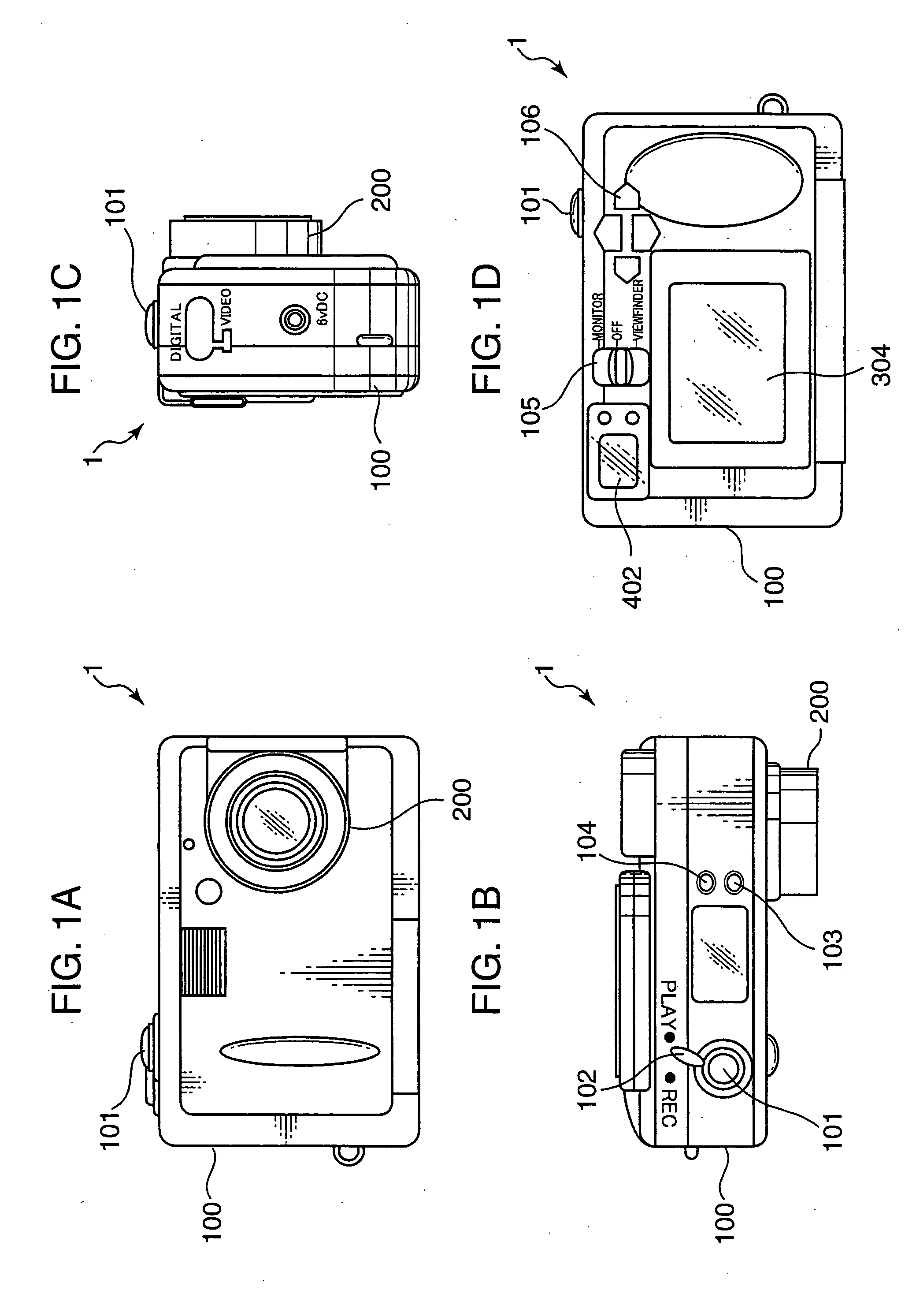
[0031]FIGS. 1A through 1D are illustrations each showing an external appearance of a digital camera 1 using a single image sensor as a first embodiment of the present invention. FIGS. 1A, 1B, 1C, and 1D are a front view, top plan view, side view, and rear view of the digital camera 1, respectively. In these drawings, a main body 100 of the camera 1 is provided with a taking lens 200 on the front surface thereof. The camera body 100 is further formed with an electronic viewfinder window 402 in an upper part on the rear surface thereof, and a display monitor 304 such as an LCD below the electronic viewfinder window 402. The electronic viewfinder window402 and the display monitor 304 are adapted to reproduce and display an image recorded in an internal recording medium while the camera 1 is in the reproduction mode, i.e., PLAY mode, and to display an electronic video image, i.e., so-called “live-view image,” of an object which is captured during a photographing stand-...

second embodiment

(Second Embodiment)

[0089] In the first embodiment, an example of using an ordinary CCD sensor as the image sensor 303 has been described. In the second embodiment, an example of using a CCD sensor having specific specifications for implementing the present invention (hereinafter, called as “image sensor 303A”) is described. The image sensor 303A is similar to the image sensor 303 in the basic construction, and, accordingly, description on the elements of the image sensor 303A identical to or similar to those of the image sensor 303 will be omitted herein. Specifically, the image sensor 303A is similar to the image sensor 303 in the basic construction except that, as shown in FIG. 13, the image sensor 303A has an imaging area 3031 which is divided into two sections, namely, a first overflow drain area V1 (hereinafter, called as the “first ODF area V1”) and a second overflow drain area V2 (hereinafter, called as the “ODF area V2”), so that a charge sweep pulses (VOFD) are suppliable t...

use example 1

( Gain Setting in AFE)

[0098] A phenomenon is known that a maximal allowable accumulative quantity of signal charges, i.e., pixel saturation voltage, hereinafter, called as “saturation voltage,” in each sensing element 303S of the image sensor 303 decreases as the temperature of the image sensor 303 rises. FIG. 15 is a graph showing an example of a relation between a temperature of an image sensor and a saturation voltage. As shown in FIG. 15, the saturation voltage is lowered linearly as the temperature of the image sensor rises. In the example of FIG. 15, whereas the saturation voltage is about 500 mV when the temperature of the image sensor is 10° C., the saturation voltage is lowered to about 370 mV when the temperature of the image sensor is 60° C.

[0099] Let it be assumed that an analog signal outputted from an image sensor to an A / D converter circuit is converted to a digital signal ranging from 0 to 1023 gradations based on a scale that the gradation is changed by one per 1 m...


PUM

PropertyMeasurementUnit
charge accumulation timeaaaaaaaaaa

Abstract

An image sensing apparatus includes: an image sensor to photoelectrically convert an object image to electrical signals; a controller to controllably read out the electrical signals generated in the image sensor; a processor to apply a predetermined image processing to the read-out electrical signals; and an estimating part to obtain a value of a dark current generated in the image sensor for estimating an internal temperature of the image sensor based on the dark current value. The image processing by the processor is altered based on the estimative value of the internal temperature of the image sensor outputted from the estimating part.

Description

[0001] The present application is based on Japanese Patent Application No. 2003-361068 filed on Oct. 21, 2003, the contents of which are hereby incorporated by references. BACKGROUND OF THE INVENTION [0002] 1. Field of the Invention [0003] The present invention relates to an image sensing apparatus, e.g., a digital camera, incorporated with an image sensor such as a CCD sensor, and more particularly to an image sensing apparatus capable of altering an image processing in an image processing section thereof, considering the temperature of the image sensor. [0004] 2. Description of the Related Art [0005] An image sensor such as a CCD sensor for photoelectrically converting an object image to electric signals is constructed such that the electrical signals are generated based on electric charges generated by receiving light reflected from an object. In the image sensor, there is likelihood that electric charges may be generated despite the fact that light is not actually received. Such...

Claims


Application Information

Patent Timeline
Patent Type & Authority Applications(United States)
IPC IPC(8): G03F3/08H04N5/335H01L27/14H04N5/353H04N5/361H04N5/376H04N9/64
CPCH04N5/361H04N5/2353H04N23/73H04N25/63
Inventor HONDA, TSUTOMUKUBO, HIROAKI
Owner KONICA MINOLTA CAMERA
Why Eureka
Try Eureka