Structure of LED illuminating apparatus

Inactive Publication Date: 2005-04-21
UNITED MICROELECTRONICS CORP
View PDF9 Cites 19 Cited by
  • Summary
  • Abstract
  • Description
  • Claims
  • Application Information

AI Technical Summary

Benefits of technology

[0015] The present invention has been made in view of the above problems, and an object of the invention is to provide an LED illuminating apparatus, which is u

Problems solved by technology

However other optical components, including the UHP mercury lamp 101 itself will be heated by the IR radiation and result in a shorter service life.
However, the light intensity is insufficient in the red wavelength region.
Part of the illumination light emitted f

Method used


Image

  • Structure of LED illuminating apparatus
  • Structure of LED illuminating apparatus
  • Structure of LED illuminating apparatus

Examples


Example

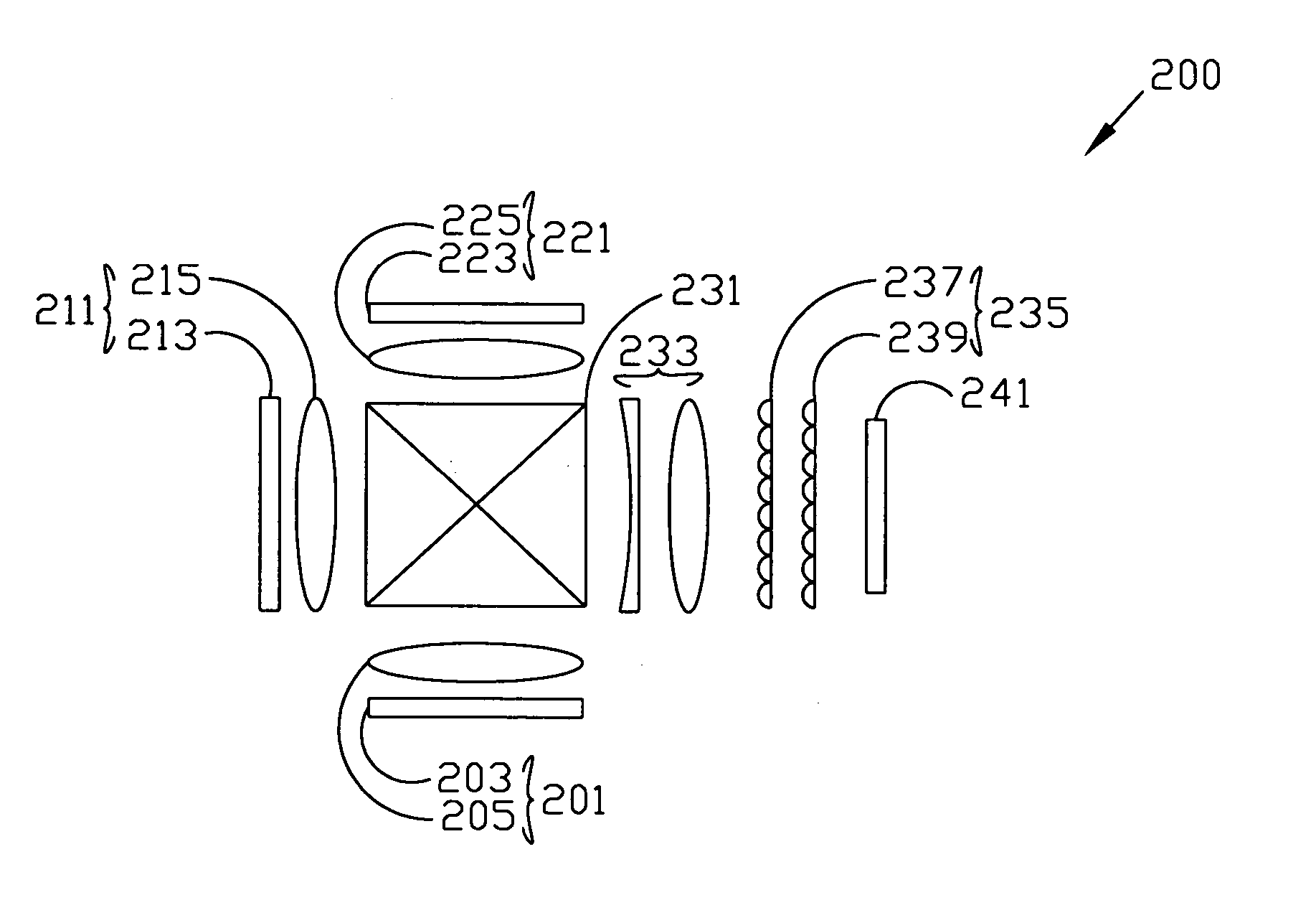
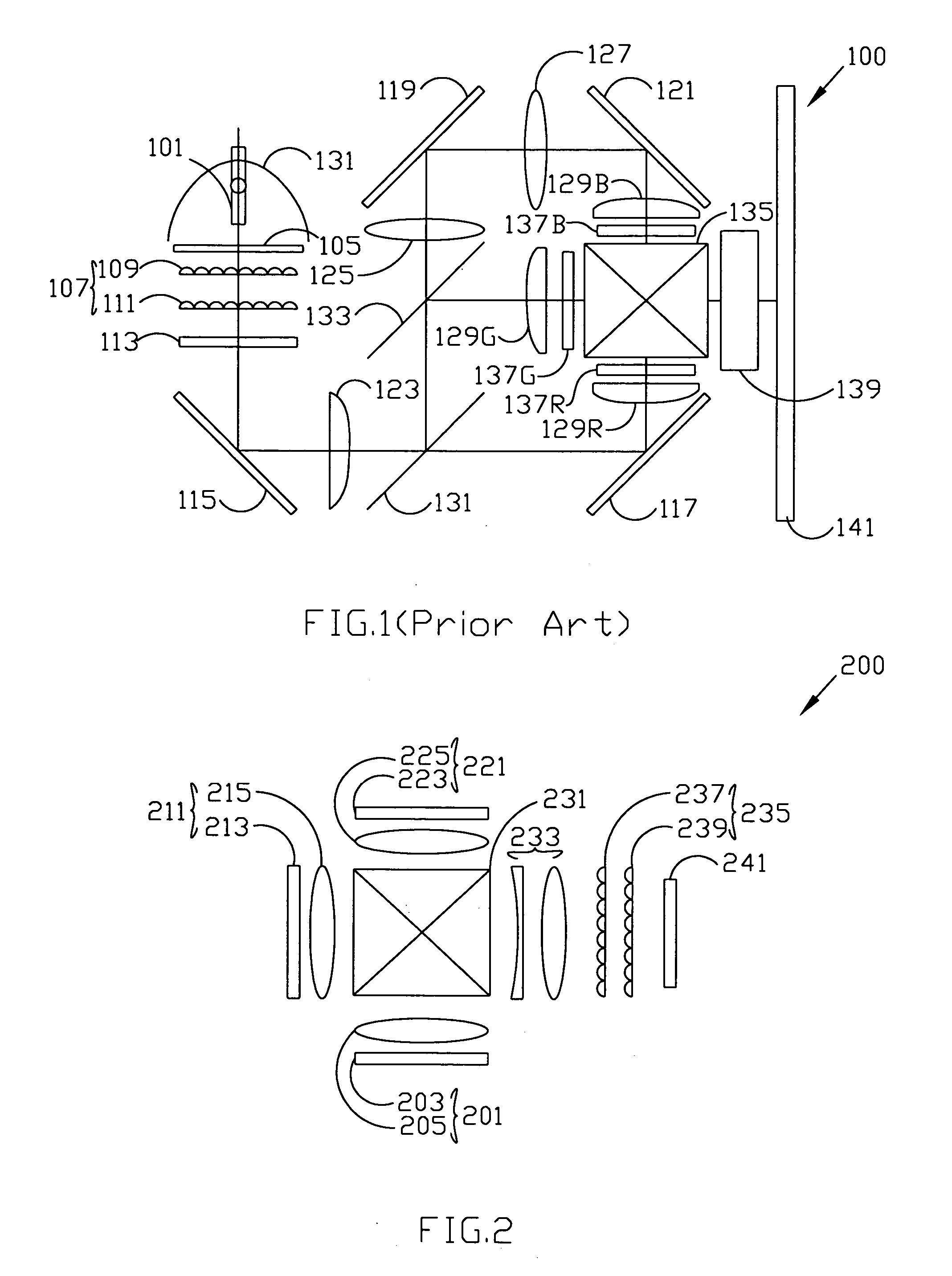
[0025]FIG. 2 is a plan showing a preferred embodiment of an LED illuminating apparatus 200 in accordance with the present invention. The LED illuminating apparatus 200 is composed of a red LED module 201, a green LED module 211, a blue LED module 221, an X-cube 231, a lens module 233, an optical integrator 235, and a polarization conversion system 241.

[0026] The red LED module 201 is composed of a red monochromatic LED array 203 and a corresponding condense lens 205. The green LED module 211 is composed of a green monochromatic LED array 213 and a corresponding condense lens 215. The blue LED module 221 is composed of a blue monochromatic LED array 223 and a corresponding condense lens 225. Three plane lights, emitted from the red, green, and blue monochromatic LED arrays 203, 213, and 223 sequentially or simultaneously, provide a steady optical throughput which passes through the corresponding condense lens 205, 215 and 225, and is collimated toward the X-cube 231. The X-cube 231 ...


PUM


Abstract

The present invention provides a structure of an LED illuminating apparatus, which is used as the light source to prevent damage to the optical components by the UV and IR radiation emitted from the conventional UHP mercury lamp. The red, green, and blue monochromatic LED arrays emit desirable wavelengths such as the primary colors rather than starting with a broadband light source and filter out the undesired wavelengths of the conventional projector.

Description

BACKGROUND OF THE INVENTION [0001] 1. Field of the Invention [0002] This invention relates to an illuminating apparatus, more particularly to an LED (light emitting diode) illuminating apparatus that is adapted for use as a light source in a projector. [0003] 2. Description of the Prior Art [0004] The projector has been used for many years to project motion pictures and still photographs onto screens for viewing. The projector has recently become a must-have business and teaching tool. Presentations using a multimedia projector are common for conducting sales demonstrations, business meetings, and classroom instruction. And as the projector is lighter, more compact than and less expensive as before, a number of customers even bring a movie theater into their home by using a state-of-the-art projector. [0005]FIG. 1 is a plan showing the structure on the optical engine of a conventional projector 100. The conventional projector 100 is composed of an illuminating system, an optical col...

Claims


Application Information

Patent Timeline
IPC IPC(8): F21V1/00G03B21/20
CPCH04N9/3105H04N9/3114G03B21/208G03B21/2033H04N9/315
Inventor CHIANG, PO-LIANGLIU, YI-WEI
Owner UNITED MICROELECTRONICS CORP
Why Eureka
Try Eureka