Full-duplex antenna system and method

a full-duplex antenna and antenna matching technology, applied in the field of full-duplex antenna systems and antenna matching circuitry, can solve the problems of insufficient design to cover all the required frequencies, affecting the performance of gps and pcs, and affecting the performance of wireless telephone communications, etc., and achieves the effect of reducing the cost of cellular band performance, and improving gps and pcs performan

Inactive Publication Date: 2005-04-21
KYOCERA CORP
View PDF99 Cites 145 Cited by
  • Summary
  • Abstract
  • Description
  • Claims
  • Application Information

AI Technical Summary

Benefits of technology

[0023] Further, the method may provide for full-duplex operation in two completely different communication bands. That is, the method may comprise effectively resonating the first antenna at a frequency selectable third channel in a second frequency band and generating a third antenna impedance at the third channel frequency. Effective...

Problems solved by technology

Such a design is not always adequate to cover all the required frequencies (communication bands), however.
However, the widening of the higher band, to improve GPS and PCS performance, comes at the expense of cellular band performance.
Another antenna-related problem stems from the duplex nature of wireless telephone communications.
For example, transmit signals that couple into the receiver raise the receiver noise floor and degrade sensitivity.
Conventional measurement techniques, however, have characterized ferroelectric components as substantially lossy, regardless of the...

Method used


Image

  • Full-duplex antenna system and method
  • Full-duplex antenna system and method
  • Full-duplex antenna system and method

Examples


Embodiment Construction

[0034] OF THE PREFERRED EMBODIMENTS

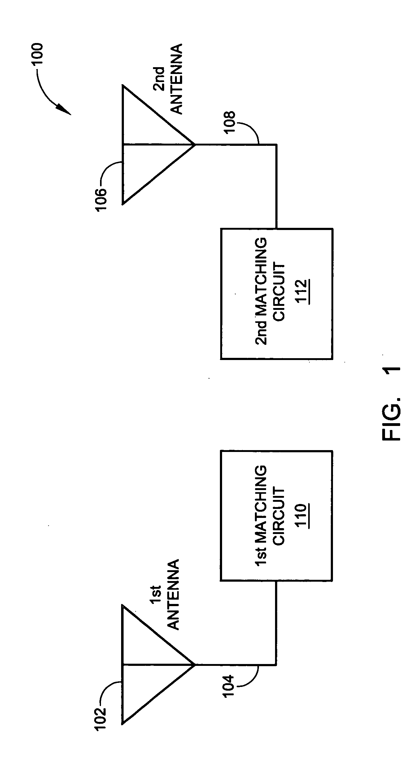
[0035]FIG. 1 is a schematic block diagram of the present invention full-duplex antenna system for selectively tuning communication channels. The system 100 comprises a first antenna 102 that is effectively resonant at a frequency selectable first channel in a first frequency band. Depending upon the communication system, the first channel has a minimum frequency span that varies from several kilohertz, to megahertz (MHz). Depending on the selectivity, the frequency span may be wide enough to cover several adjacent channels. The first antenna 102 has an interface port on line 104 with a first impedance at the first channel frequency.

[0036] A second antenna 106 is effectively resonant at a frequency selectable second channel in the first frequency band. The second antenna 106 has an interface on line 108 with a second impedance at the second channel frequency. A first matching circuit 110 includes a port connected on line 104 to the first antenna i...


PUM


Abstract

A system and method is provided for full-duplex antenna impedance matching. The method comprises: effectively resonating a first antenna at a frequency selectable first channel in a first frequency band; generating a first antenna impedance at the first channel frequency; effectively resonating a second antenna at a frequency selectable second channel in the first frequency band; generating a second antenna impedance at the second channel frequency; supplying a first conjugate impedance match at the first channel frequency; and, supplying a second conjugate impedance match at the second channel frequency. For example, the first antenna may be used for transmission, while the second antenna is used for received communications. The antennas effectively resonant in response to: supplying frequency selectable conjugate impedance matches to the antennas; generating frequency selectable antenna impedances; and/or selecting the frequency of antenna resonance.

Description

RELATED APPLICATIONS [0001] This application is related to and is a continuation-in-part of U.S. applications “FERROELECTRIC ANTENNA AND METHOD FOR TUNING SAME”, Ser. No. 10 / 117,628, filed on Apr. 4, 2002; “INVERTED-F FERROELECTRIC ANTENNA”, Ser. No. 10 / 120,603, filed on Apr. 9, 2002; and “TUNABLE ANTENNA MATCHING CIRCUIT”, Ser. No. 10 / 075,896, filed on Feb. 12, 2002, all of which are incorporated herein by reference. [0002] This application is related to U.S. APPLICATIONS “TUNABLE HORN ANTENNA”, Ser. No. 10 / 122,399, filed on Apr. 12, 2002; “TUNABLE WAVEGUIDE ANTENNA”, Ser. No. 10 / 122,968, filed on Apr. 11, 2002; “TUNABLE DIPOLE ANTENNA”, Ser. No. 10 / 121,773, filed on Apr. 11, 2002; and “TUNABLE MATCHING CIRCUIT”, Ser. No. 09 / 927,136, filed on Aug. 10, 2001, all of which are incorporated herein by reference. [0003] This application is also related to the following two U.S. applications filed on the same day as the present application and having the same inventors, and which applicat...

Claims


Application Information

Patent Timeline
IPC IPC(8): H01P5/04H01Q1/00H01Q1/24H01Q9/04H01Q9/16H01Q9/30H01Q9/42H01Q13/02H01Q13/06H01Q13/20H01Q13/22
CPCG01R27/2694H03H7/40H01L27/0808H01P1/203H01P1/20336H01P1/20363H01P1/20381H01P1/2039H01P1/2056H01P1/213H01P5/04H01Q1/00H01Q1/243H01Q3/44H01Q9/0407H01Q9/0421H01Q9/0442H01Q9/16H01Q9/28H01Q9/30H01Q9/42H01Q13/02H01Q13/06H01Q13/203H01Q13/22H03B5/04H03B5/1841H03B5/362H03F1/56H03F3/191H03F2200/294H03F2200/372H03H7/0123H03H7/12H03H7/20H03J5/246H03L1/022H03L7/18H04B1/0053H04B1/0458H04B1/30H01G7/06H04B1/18
Inventor POILASNE, GREGORYFABREGA-SANCHEZ, JORGETONCICH, STANLEY S.TRAN, ALLEN
Owner KYOCERA CORP
Why Eureka
Try Eureka