
Heat pipe for cautery surgical instrument

a technology of cautery and heat pipe, which is applied in the field of improved temperature control mechanisms of cautery devices, can solve the problems of inability to achieve effective effects, danger of ‘malignant’ or ‘runaway’ hyperthermia, and inability to regulate the mechanism of body temperatur

Inactive Publication Date: 2005-04-21
THERMAL
View PDF25 Cites 92 Cited by
  • Summary
  • Abstract
  • Description
  • Claims
  • Application Information

AI Technical Summary

Problems solved by technology

While tissue heating is the mechanism by which the various cautery surgical treatments are effected, it can also cause nonefficacious effects.
), the mechanism that regulates body temperature can become incapacitated, and there is danger of ‘malignant’ or ‘runaway’ hyperthermia.
As a consequence, surgeons often operate prior electrosurgical devices at a very low power level.
Unfortunately, it also requires the surgeon to perform the procedure much more slowly than he would if he could operate the device at full power.
As a result, the procedure takes much longer, requiring more operating room time.
It should be noted that Levine's heat pipe assembly is one piece that requires complete immersion of the utensil in a sterilization system for cleaning, thus reducing it's working life.

Method used


Image

  • Heat pipe for cautery surgical instrument
  • Heat pipe for cautery surgical instrument
  • Heat pipe for cautery surgical instrument

Examples


Embodiment Construction

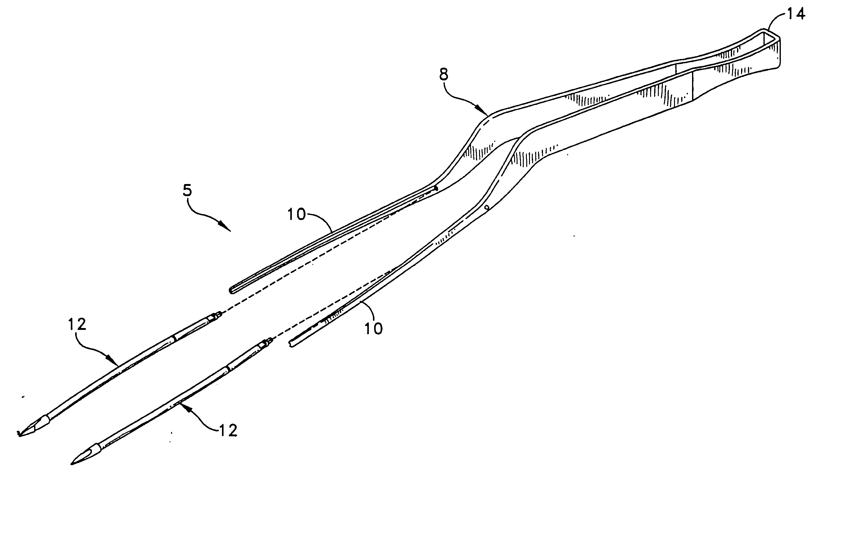
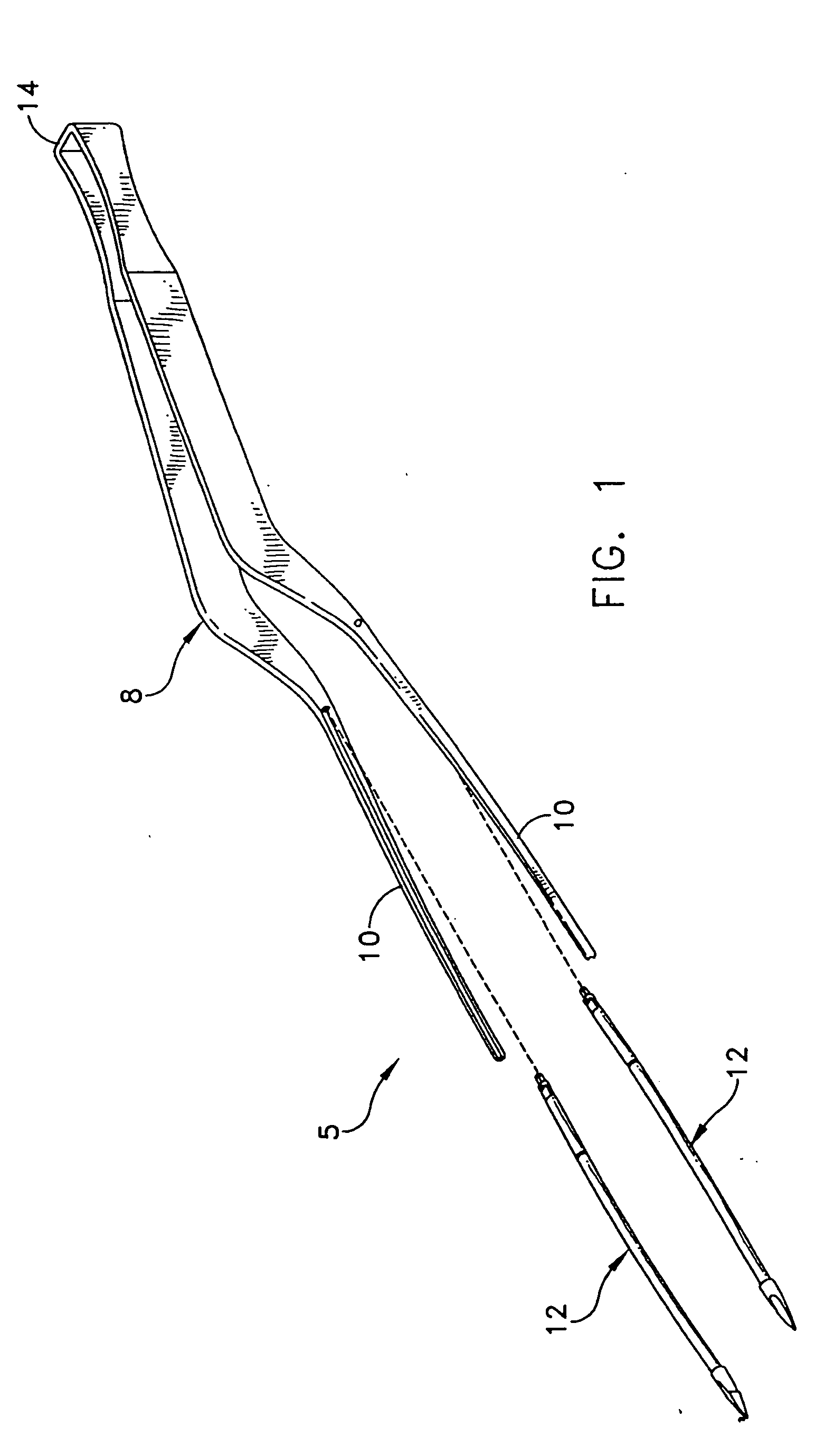
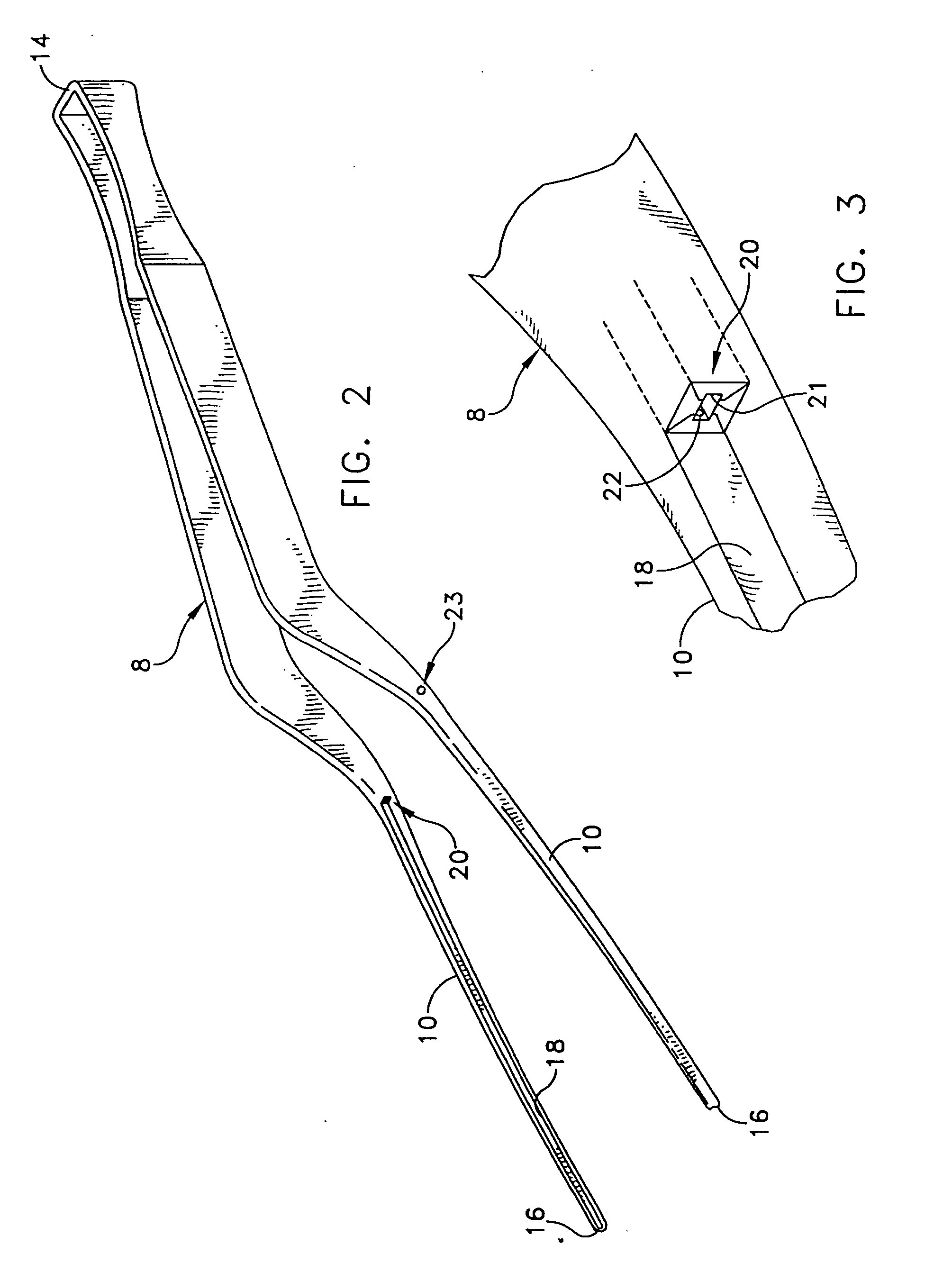
[0026] This description of preferred embodiments is intended to be read in connection with the accompanying drawings, which are to be considered part of the entire written description of this invention. The drawing figures are not necessarily to scale and certain features of the invention may be shown exaggerated in scale or in somewhat schematic form in the interest of clarity and conciseness. In the description, relative terms such as “horizontal,”“vertical,”“up,”“down,”“top” and “bottom” as well as derivatives thereof (e.g., “horizontally,”“downwardly,”“upwardly,” etc.) should be construed to refer to the orientation as then described or as shown in the drawing figure under discussion. These relative terms are for convenience of description and normally are not intended to require a particular orientation. Terms including “inwardly” versus “outwardly,”“longitudinal” versus “lateral” and the like are to be interpreted relative to one another or relative to an axis of elongation, o...


PUM


Abstract

A heat pipe for a cautery surgical instrument such as a surgical forceps including a pair of elongate arms joined at an end so as to provide for resilient compressible movement of the arms between a normally open position and a squeezed closed position. The heat pipe provides for conduction of heat away from an electrode tip, and comprises an evaporator portion having a first diameter and a condenser portion spaced away from the evaporator end, and that transitions from the first diameter to at least one smaller diameter section. A socket is disposed within each arm of the forceps, and includes a longitudinal blind hole that is sized so as to releasably receive the smaller diameter section of the condenser portion, and a catch for engaging a portion of the arm.

Description

FIELD OF THE INVENTION [0001] The present invention generally relates to medical devices and, more particularly, to improved temperature control mechanisms for cautery devices using heat pipes. BACKGROUND OF THE INVENTION [0002] Medical treatments today often require that areas of organic tissue be cauterized or coagulated quickly, efficiently, and safely during the course of a surgical procedure. For example, surface tissue on a highly vascularized organ such as the human liver or brain may be cauterized immediately following the making of a surgical incision in order to prevent excessive bleeding. Alternatively, retinal tissue in a human eye may be photocoagulated during opthalmic surgery to correct injury or, skin tissue on a human scalp may be coagulated during hair transplant surgery to prevent bleeding resulting from graft incisions. Many prior art devices have been developed to perform cauterization or coagulation as appropriate for such varied applications. Known devices ran...

Claims


Application Information

Patent Timeline
Patent Type & Authority Applications(United States)
IPC IPC(8): A61B18/00A61B18/14A61B18/18
CPCA61B18/1442A61B2018/1462A61B2018/00095A61B2018/00005
Inventor MUCKO, DAVID JOSEPHBILSKI, WALTER JOHN
Owner THERMAL
Learn More