Speed-adaptive control scheme for legged running robots

Inactive Publication Date: 2005-04-21
MASSACHUSETTS INST OF TECH
View PDF0 Cites 81 Cited by
  • Summary
  • Abstract
  • Description
  • Claims
  • Application Information

AI Technical Summary

Benefits of technology

[0011] With this particular arrangement, a control technique which does not use instantaneous apex height to calculate a leg angle is provided. Rather, in the technique of the present invention, the leg rotates continuously after apex until touch-down occurs. According to a calculated time series of the leg angle, at any possible instant of t

Problems solved by technology

However, even with sufficiently controlled system energy, forward locomotion may fail.
If a leg is not properly aligned with respect to the ground level (e.g. the ground is higher than expected), the legged system can stumble or fall over.
Although this decomposed control can result in dynamically stable locomotion, it inherits several difficulties.
Second, as it presets the legs in one

Method used


Image

  • Speed-adaptive control scheme for legged running robots
  • Speed-adaptive control scheme for legged running robots
  • Speed-adaptive control scheme for legged running robots

Examples


Example

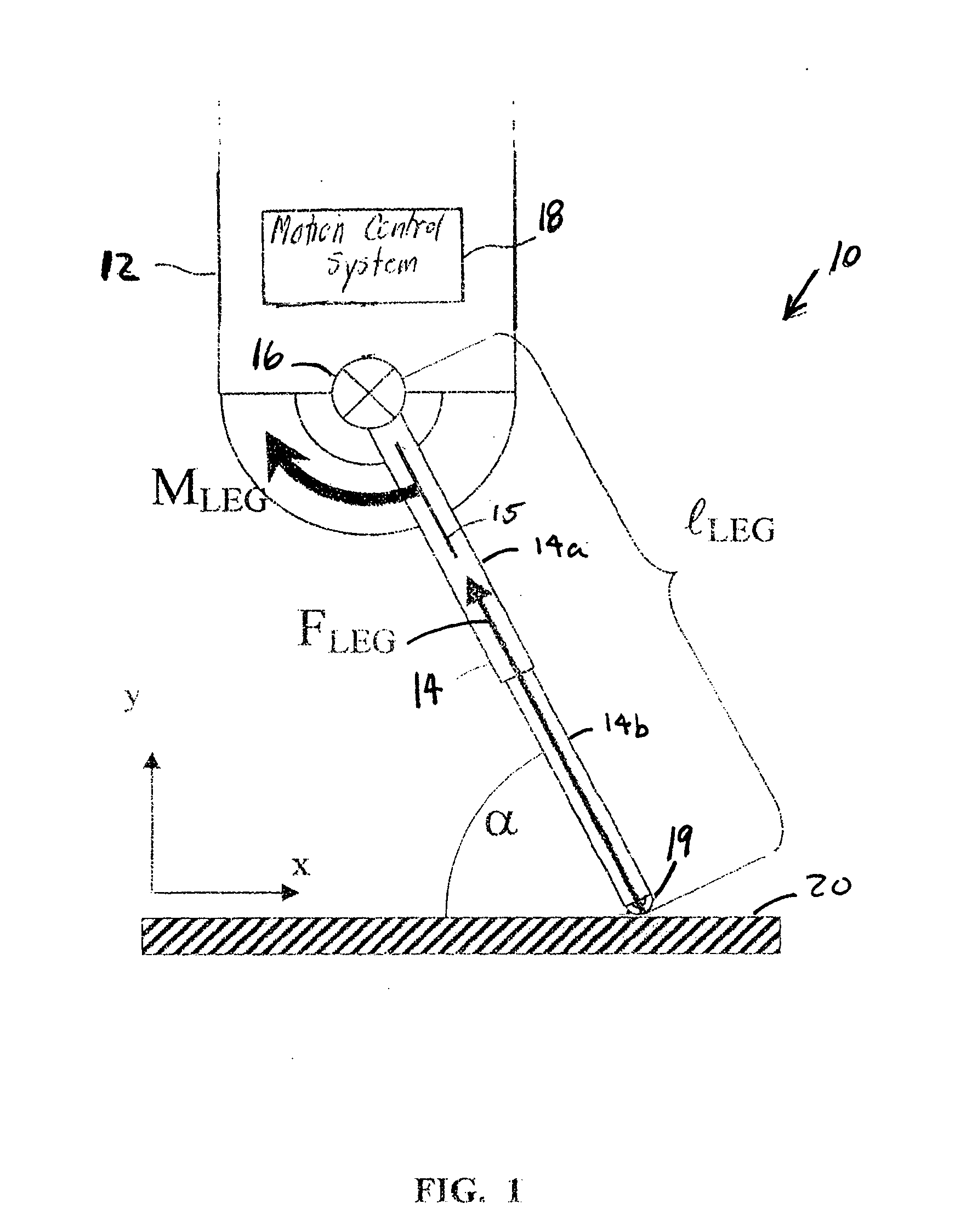
[0025] Exemplary embodiments of the invention will now be explained using a monopod robot as an example of a legged robot. It should be appreciated that the monopod robot of FIG. 1 is intended to merely serve as an example of a legged running machine with which the control system of the present invention can be used and that the control system of the present invention also finds use with a variety of other types of legged running machines. It should also be appreciated that numerous details are set forth below in order to provide a thorough understanding of the control techniques and related apparatus used to provide robot locomotion. It should be apparent to one of ordinary skill in the art that variants of the below described techniques and apparatus may be used in other embodiments without deviating from the spirit and scope of the concepts described herein. For example, the concepts described below can be implemented in robots having one, two, three or any number of legs. It sho...


PUM


Abstract

A control scheme for legged running machines which is based on a decoupled control of system energy and kinematic trajectory is described.

Description

CROSS REFERENCE TO RELATED APPLICATIONS [0001] This application claims the benefit under 35 U.S.C. §119(e) of U.S. Provisional Application No. 60 / 437,703, filed on Dec. 31, 2002, entitled, Speed-Adaptive Control Scheme for Legged Running Robots, which is hereby incorporated by reference in its entirety.STATEMENT REGARDING FEDERALLY SPONSORED RESEARCH [0002] Not applicable. BACKGROUND OF THE INVENTION [0003] This invention relates to a control scheme for controlling the locomotion of a legged robot, and more particularly to a control scheme stabilizing any desired, energetically possible movement trajectory at any given locomotion speed within a single step of a running monopod or other legged robot. [0004] Legged locomotion aims to move an object in an intended direction. To achieve this goal, the system must provide enough energy to compensate for losses within the system (e.g. leg damping) and with the environment (e.g. air friction). Thus, legged robots require a control, which k...

Claims


Application Information

Patent Timeline
IPC IPC(8): B62D57/032G06F19/00
CPCB62D57/032
Inventor HERR, HUGHSEYFARTH, ANDREGEYER, HARTMUT
Owner MASSACHUSETTS INST OF TECH
Why Eureka
Try Eureka