Car control device electronics

a technology of electronic control device and control device, which is applied in the direction of braking system, process and machine control, instruments, etc., can solve the problems of limited use of electropneumatic-pneumatic valves in freight trains

Inactive Publication Date: 2005-04-21
NEW YORK AIR BRAKE CORP
View PDF7 Cites 21 Cited by
  • Summary
  • Abstract
  • Description
  • Claims
  • Application Information

AI Technical Summary

Problems solved by technology

Thus, the use of electropneumatic-pneumatic valves in the freight trains has been very limited.

Method used


Image

  • Car control device electronics
  • Car control device electronics
  • Car control device electronics

Examples


Embodiment Construction

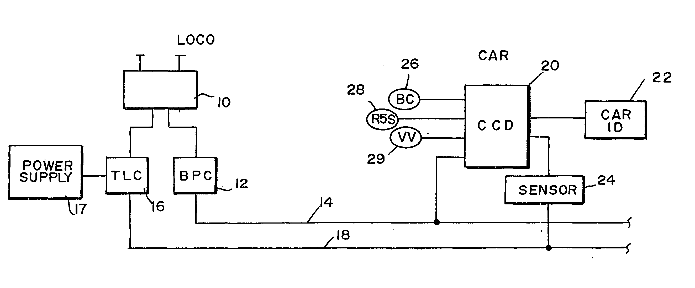
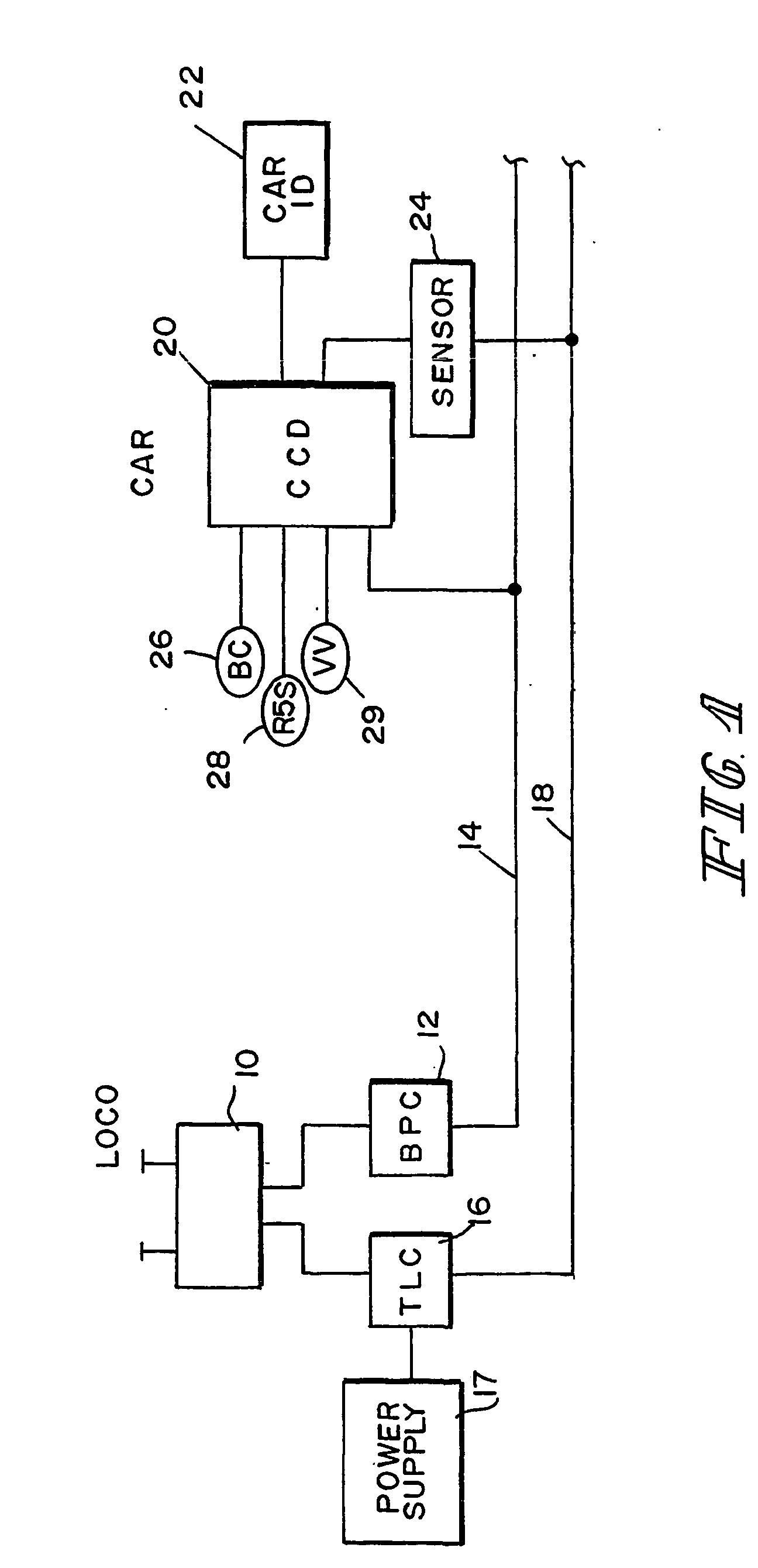
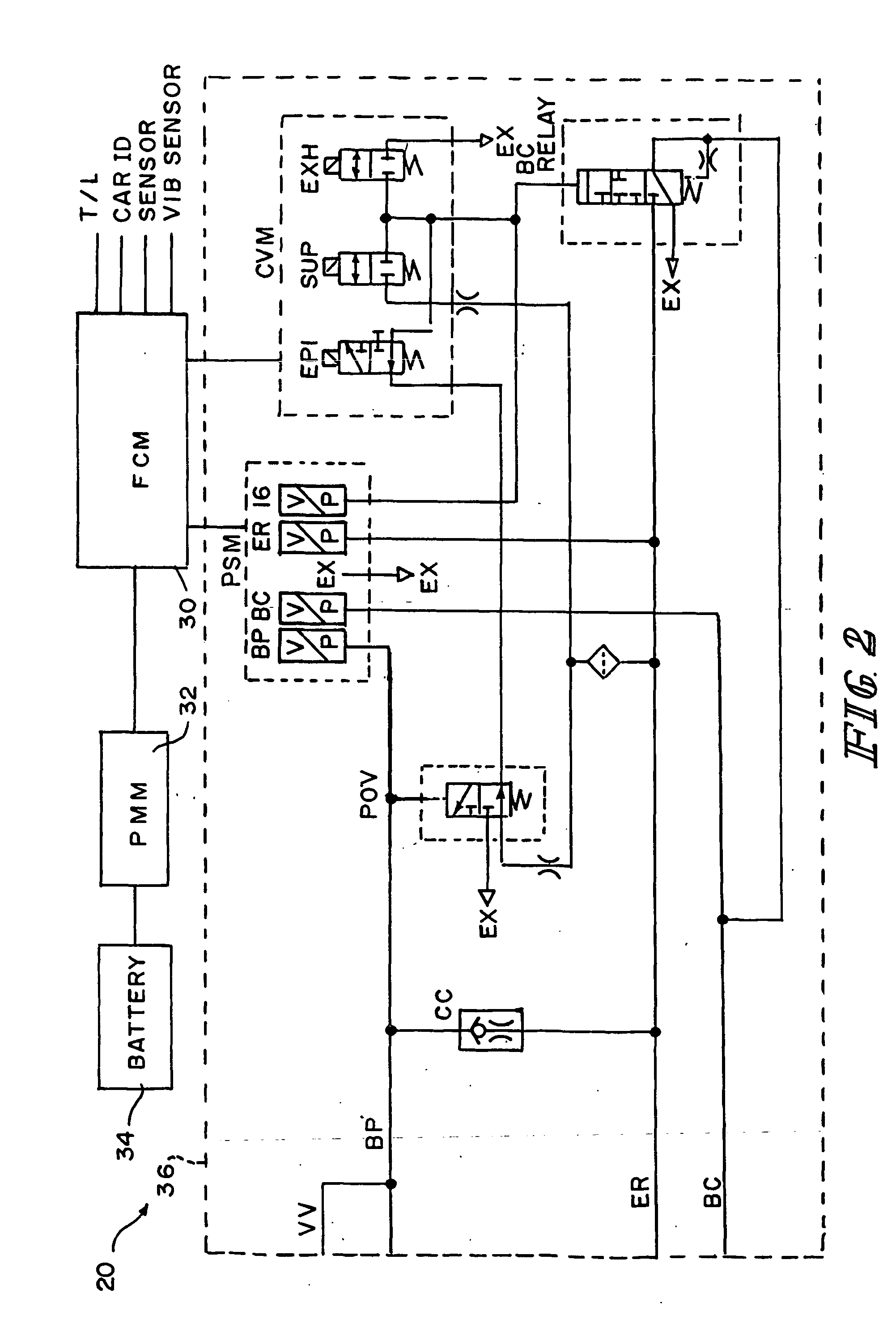
[0012] The car control device 20 is shown in detail in FIG. 2. It includes a functional control module 30 which is connected to the trainline T / L to receive power off the trainline 18 as well as to communicate to the trainline controller 16 over the trainline. It also provides power and communication to the car ID 22, the sensor 24 and a vibration sensor (not shown). Other auxiliary devices, for example, empty / load, hot wheel detector, may be connected to and powered by the CCD20. As described in the Lumbis U.S. Pat. No. 6,049,296, the car ID 22 and its sensor are used in an automatic train serialization. The car vibration sensor preferably is within the car control device 20 for added protection reduced wire length and improved accuracy of measurement.

[0013] The car control device 20 also includes a power management module 32 connected to the functional control module 30 to control the charging of battery 34. The battery is charged off the trainline T / L and used in combination wit...


PUM


Abstract

An electronic control system (20) for an electropneumatic brake for a rail vehicle having a power trainline (18), comprising a battery (34); a functional control module (30) and a power management module; wherein the functional control module (30) includes a brake controller for the electropneumatic brake, an interface to the power trainline, a transceiver for receiving brake signals, a power supply circuit deriving a power supply from the power trainline (18), and a control management controller for the transceiver and the power supply circuit; and wherein the power management module includes a battery charging circuit connected to the power supply and a power controller for the battery charging circuit and the power supply circuit.

Description

BACKGROUND AND SUMARY OF THE INVENTION [0001] The present invention relates to electropneumatic brake control on a train and more specifically to the electronic portion of the car electropneumatic brake control. [0002] Electropneumatic brake control valves are well known in the passenger railroad art and the mass transit railroad art. Because the trains are short and are not involved generally in a mix and match at an interchange of different equipment the ability to provide pneumatic and electrical control throughout the train has been readily available in the passenger and the mass transit systems. In freight trains, the trains may involve as much as 100 cars stretching over one mile or more. The individual cars may lay idle in harsh environments for up to a year without use. Also, because of the long distance they travel, the cars are continuously moved from one consist to another as it travels to its destination. Thus, the use of electropneumatic-pneumatic valves in the freight ...

Claims


Application Information

Patent Timeline
Patent Type & Authority Applications(United States)
IPC IPC(8): B60T8/17B60T13/66B60T13/68B60T17/22B61H9/00
CPCB60T8/1705B60T13/662B61H9/00B60T13/683B60T17/228B60T13/665Y02T30/00
Inventor LUMBIS, ANTHONY WSTEVENS, DALE RVERSIC, JOHN N
Owner NEW YORK AIR BRAKE CORP
Why Eureka
Try Eureka