Engine valve actuation system

a technology of engine valves and actuators, applied in the direction of valve details, valve arrangements, valve drives, etc., can solve the problems of reducing the overall efficiency of the engine, generating undesirable emissions, and eventually exhausted undesirable emissions to the environmen

Inactive Publication Date: 2005-04-28
CATERPILLAR INC
View PDF35 Cites 36 Cited by
  • Summary
  • Abstract
  • Description
  • Claims
  • Application Information

AI Technical Summary

Benefits of technology

[0010] In another aspect, the present disclosure is directed to a method of actuating an engine valve having a first position at which the engine valve prevents a flow of fluid relative to the engine valve and a second position at which the fluid flows relative to the engine valve. A first cam is rotated to engage a cam follower associated with the engine valve to thereby move the engine valve between the first position and the second position during a first lift period. A second cam is rotated to engage the cam follower to thereby affect movement of the engine valve between the first position and the second position during a second lift period. The rotational phase of the second cam is adjusted to thereby adjust the relative timing between the first lift period and the second lift period.

Problems solved by technology

The operation of an internal combustion engine such as, for example, a diesel, gasoline, or natural gas engine, may cause the generation of undesirable emissions.
If no emission reduction measures are in place, these undesirable emissions will eventually be exhausted to the environment.
Unfortunately, the implementation of these emission reduction approaches typically results in a decrease in the overall efficiency of the engine.
However, while valve actuation timing adjustments may provide efficiency benefits, these actuation timing adjustments may also result in detrimental engine performance under certain operating conditions.
For example, a late intake Miller cycle may be inefficient when the engine is starting, operating under cold conditions, or experiencing a transient condition, such as a sudden increase in engine load.
This detrimental engine performance is caused by a decrease in the mass of air flowing through the engine.
Especially under cold ambient conditions, the delayed start of compression may lead to cylinder temperatures insufficient to support good combustion and startability.
Because the shape of the cam is fixed, this type of arrangement is inflexible and may only be changed during the operation of the engine through the use of complex mechanical mechanisms.

Method used


Image

  • Engine valve actuation system
  • Engine valve actuation system
  • Engine valve actuation system

Examples


Embodiment Construction

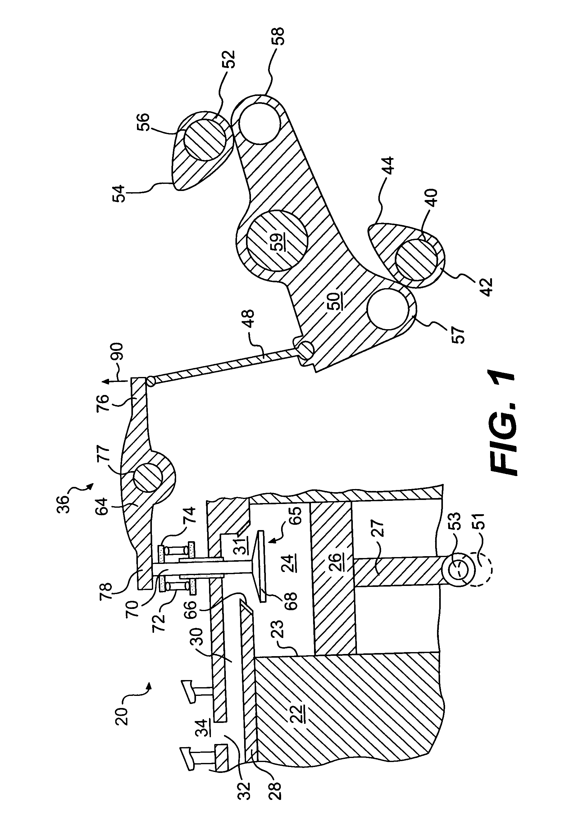
[0015] An exemplary embodiment of an engine 20 is schematically and diagrammatically illustrated in FIG. 1. Engine 20 includes an engine block 22 that defines a plurality of cylinders 23 (one of which is illustrated in FIG. 1). A piston 26 is slidably disposed within cylinder 23 to reciprocate between a top-dead-center position and a bottom-dead-center position.

[0016] For the purposes of the present disclosure, engine 20 is described as a four-stroke diesel engine. One skilled in the art will recognize, however, that engine 20 may be any other type of internal combustion engine such as, for example, a gasoline or natural gas engine.

[0017] A connecting rod 27 connects piston 26 to an eccentric crankpin 53 of a crankshaft 51. Piston 26 is coupled to crankshaft 51 so that a movement of piston 26 between the top-dead-center position and the bottom-dead-center position results in a rotation of crankshaft 51. Similarly, a rotation of crankshaft 51 will result in a movement of piston 26 ...


PUM


Abstract

A valve actuation system includes an engine valve moveable between a first position at which engine valve prevents a flow of fluid relative to the engine valve second position at which the fluid flows relative to the engine valve. The system also has a cam follower operatively connected to the engine valve. A first cam is adapted to engage the cam follower such that the rotation of the first cam acts to move the engine valve from the first position to the second position during a first lift period. A second cam is adapted to engage the cam follower such that a rotation of the second cam acts to affect movement of the engine valve between the first position and the second position during a second lift period. A phase shifting device is operatively connected to the second cam and adapted to adjust the relative timing between the first lift period and the second lift period.

Description

TECHNICAL FIELD [0001] The present invention is directed to a system and method for actuating an engine valve and, more particularly, to a variable engine valve actuation system. BACKGROUND [0002] The operation of an internal combustion engine such as, for example, a diesel, gasoline, or natural gas engine, may cause the generation of undesirable emissions. These emissions, which may include particulates and oxides of nitrogen (NOx), are generated when fuel is combusted in a combustion chamber of the engine. An exhaust stroke of the engine piston forces exhaust gas, which may include these emissions, from the engine. If no emission reduction measures are in place, these undesirable emissions will eventually be exhausted to the environment. [0003] Research is currently being directed towards decreasing the amount of undesirable emissions that are exhausted to the environment during the operation of the engine. It is expected that improved engine design and improved control over engin...

Claims


Application Information

Patent Timeline
Patent Type & Authority Applications(United States)
IPC IPC(8): F01L1/34F01L1/344F01L13/00
CPCF01L1/08F01L13/0047F01L1/34403F01L1/146
Inventor HARMON, MICHAEL PATRICK
Owner CATERPILLAR INC
Why Eureka
Try Eureka