Radiant tube and convection oven

a technology of convection oven and radiant tube, which is applied in the direction of gaseous heating fuel, stoves or ranges, household stoves, etc., can solve the problems of considerable expense and achieve the effect of preventing overheating of light metal parts

Inactive Publication Date: 2005-04-28
GM GLOBAL TECH OPERATIONS LLC
View PDF10 Cites 20 Cited by
  • Summary
  • Abstract
  • Description
  • Claims
  • Application Information

AI Technical Summary

Benefits of technology

[0009] In the radiant bring-up section or zone, radiant tubes extend through the radiant bring-up zone preferably adjacent an intersection between the side wall and the bottom wall of the oven having a generally horizontal metal shield located above the radiant tube heaters to prevent overheating of the light metal parts of the vehicle body located above the radiant tubes. In a more preferred embodiment, the radiant bring-up zone als

Problems solved by technology

As will be understood by those skilled in this art, restarting a paint oven after shut down because of a failure of either a burner or

Method used


Image

  • Radiant tube and convection oven
  • Radiant tube and convection oven
  • Radiant tube and convection oven

Examples


Embodiment Construction

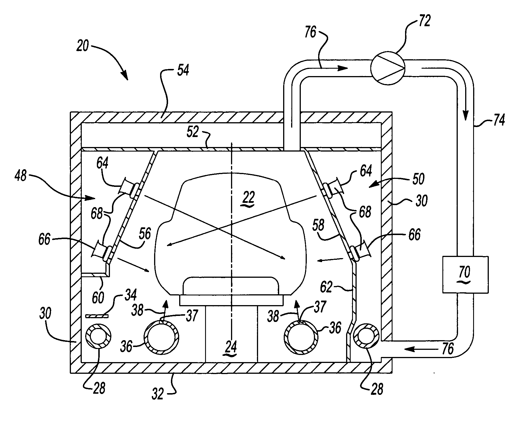
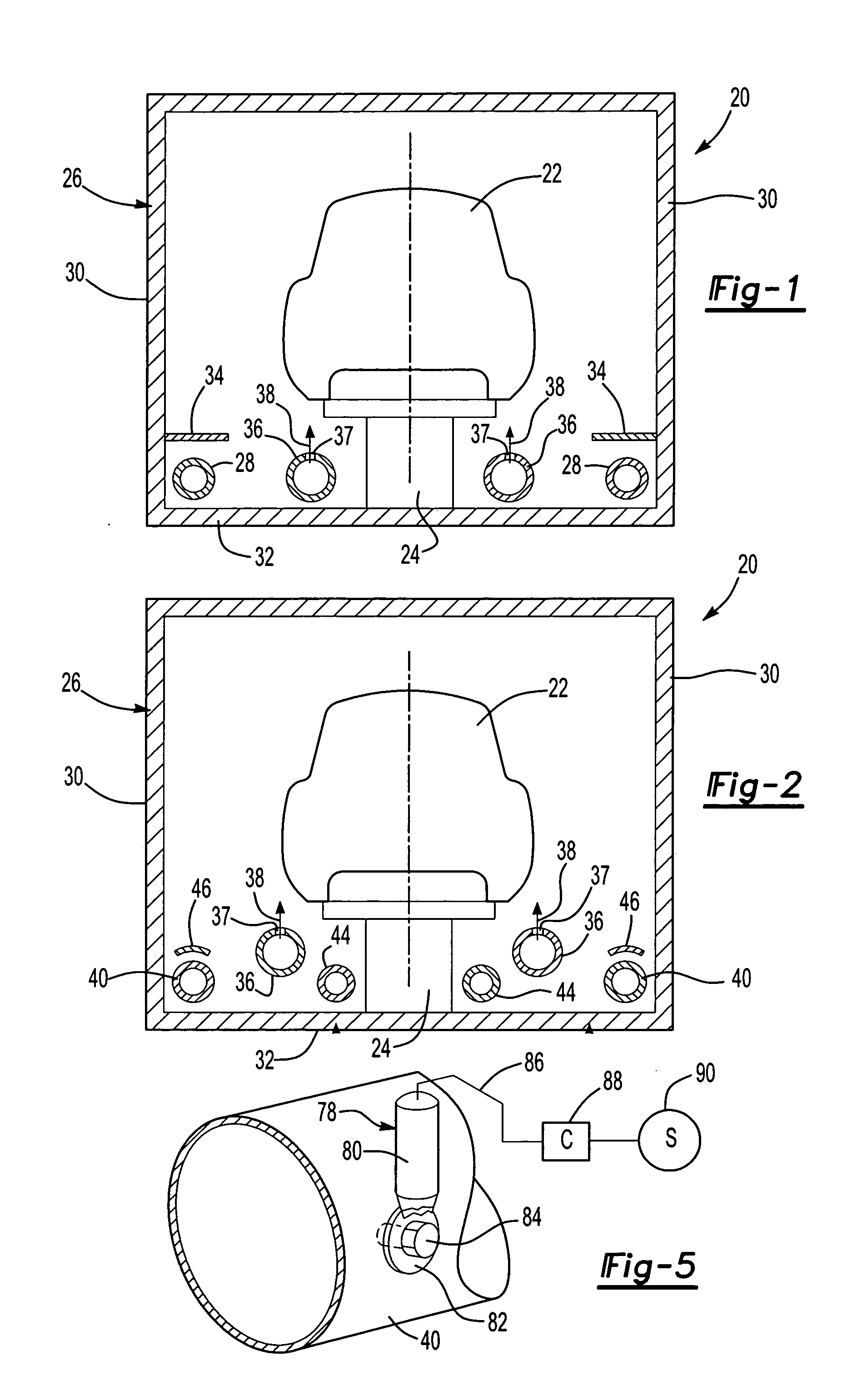
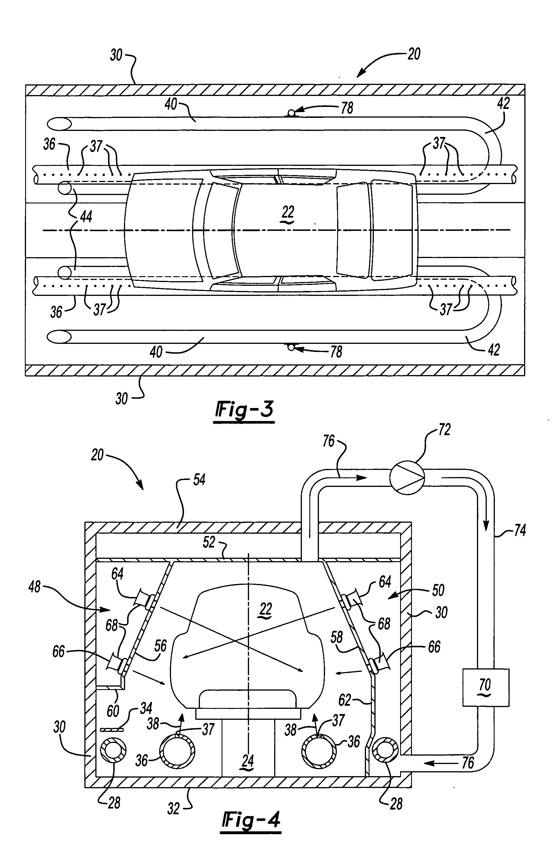
[0018] The radiant tube and convection oven 20 of this invention may be utilized to cure or bake paint or other coatings on various substrates, such as the automotive body 22, which are conveyed through the oven on a conveyor 24 generally through the longitudinal axis of the oven 20. The radiant tube and convection oven of this invention includes three zones, including a radiant bring-up zone, a convection or convective bring-zone and a hold zone. In a preferred embodiment, the three zones are coaxially or linearly aligned, such that the outer wall 26 of the oven 20 encloses all three zones and the conveyor 24 conveys the automotive body 22 through all three zones of the oven 20. As will be understood by those skilled in this art, however, the radiant tube and convection oven of this invention may include more than three zones, but preferably includes at least three zones.

[0019]FIG. 1 illustrates one embodiment of the first zone of the radiant and convection oven of this invention,...


PUM


Abstract

An oven for heating a coating on a substrate, such as a painted vehicle body, including a first zone having radiant tubes and shields above the tubes and a second zone including side heat chambers having nozzles directing heated air onto a coated substrate and a hold zone. The radiant tubes may include a first linear portion extending through the oven and return loop beneath the substrate to conserve energy and sill ducts directing heated air against the underside of the vehicle body. The temperature is controlled by sensors contacting the radiant tubes and a proportional integral control system.

Description

RELATED APPLICATIONS [0001] This application claims priority to U.S. Provisional Patent Application Ser. No. 60 / 513,748 filed Oct. 23, 2003.BACKGROUND OF THE INVENTION [0002] At present, paint and other coatings are baked or cured in a radiant oven, wherein the walls and / or floor are heated by combustion burners. In a typical automotive application, the painted vehicle body is conveyed through the radiant oven and the opposed side walls and generally the floor of the oven are heated by combustion burners which direct hot air into rectangular enclosures defining the side and bottom walls of the oven. This method of heating requires flame sensors to avoid a potential explosion in the event that a burner fails and combustible gas is directed into the enclosures which automatically turn off the flow of combustible gas to the burners and thus the enclosures, shutting down the oven. The enclosures must then be purged of combustible gas before restarting the burners and restarting the oven...

Claims


Application Information

Patent Timeline
IPC IPC(8): F26B3/28F26B3/30F26B17/12F26B21/10F26B23/02
CPCF26B21/10F26B2210/12F26B2200/06F26B23/02
Inventor KLOBUCAR, JOSEPH M.COLE, DAVID J.ROESLER, BRUCESMITH, DOUGLAS G.D' ALTENA, ADRIEN DE BORCHGRAVEPAKKALA, JAMES L.
Owner GM GLOBAL TECH OPERATIONS LLC
Why Eureka
Try Eureka