Heat dissipation module with a pair of fans

Inactive Publication Date: 2005-04-28
MOLEX INC
View PDF8 Cites 42 Cited by
  • Summary
  • Abstract
  • Description
  • Claims
  • Application Information

AI Technical Summary

Benefits of technology

[0004] One object of the present invention is to modularize a heat dissi

Problems solved by technology

Due to the closed casing of the electrical products, heat dissipation is also more difficult than before dissipation successfully and efficiently can help electrical products have a higher performance.
However, the dissipating devices are not modularized, so the fans are not easily set on

Method used


Image

  • Heat dissipation module with a pair of fans
  • Heat dissipation module with a pair of fans
  • Heat dissipation module with a pair of fans

Examples


Embodiment Construction

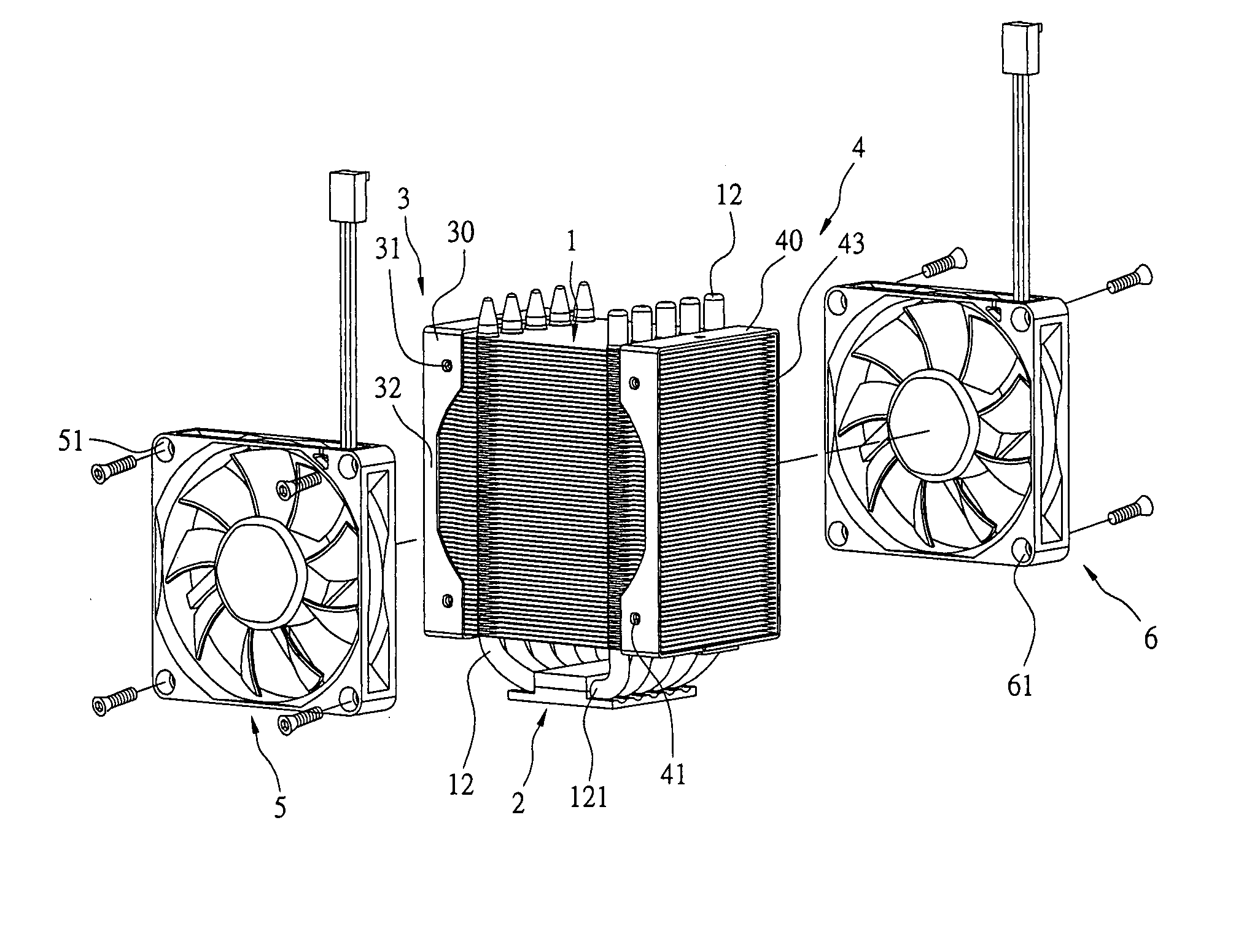
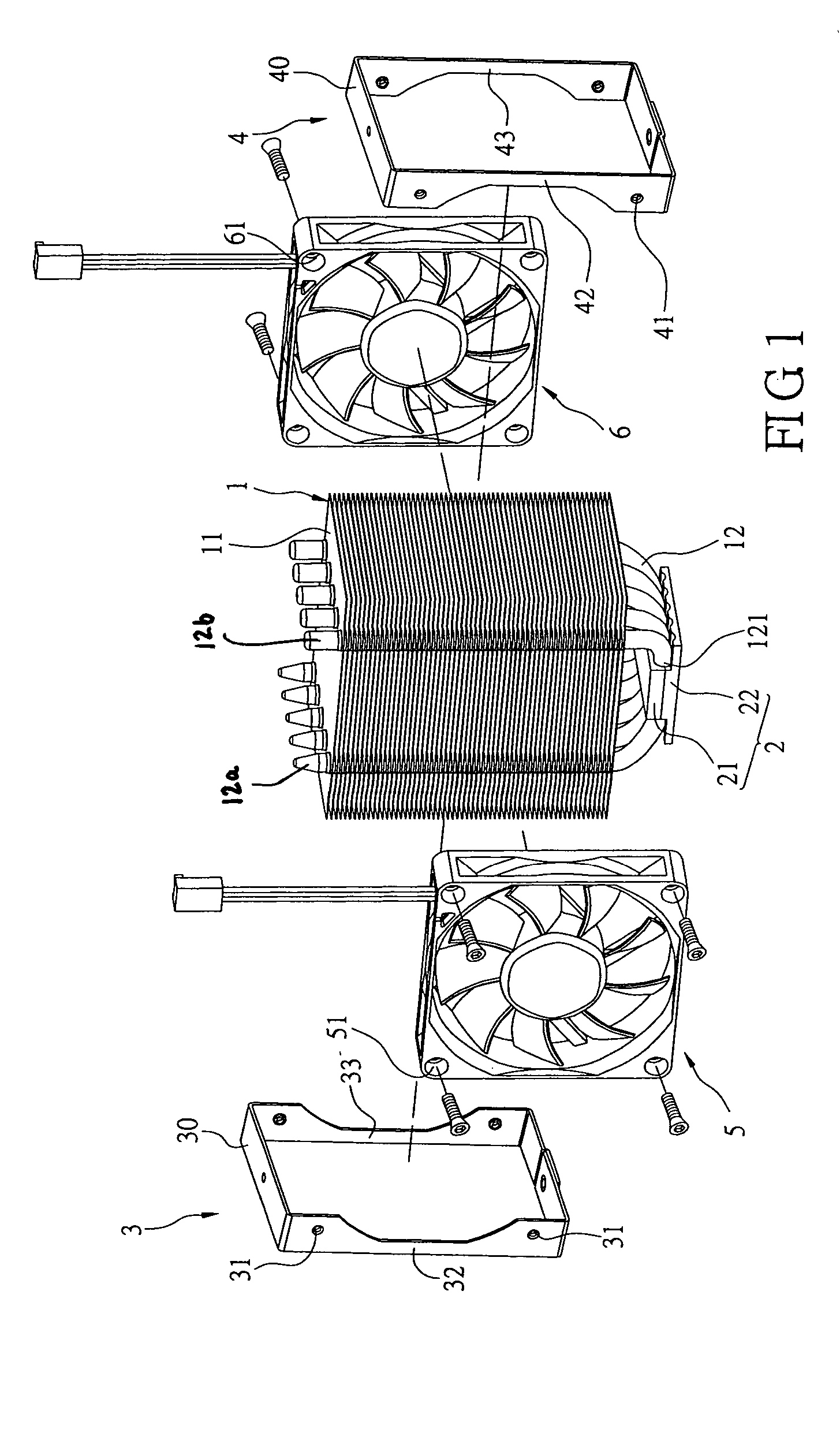
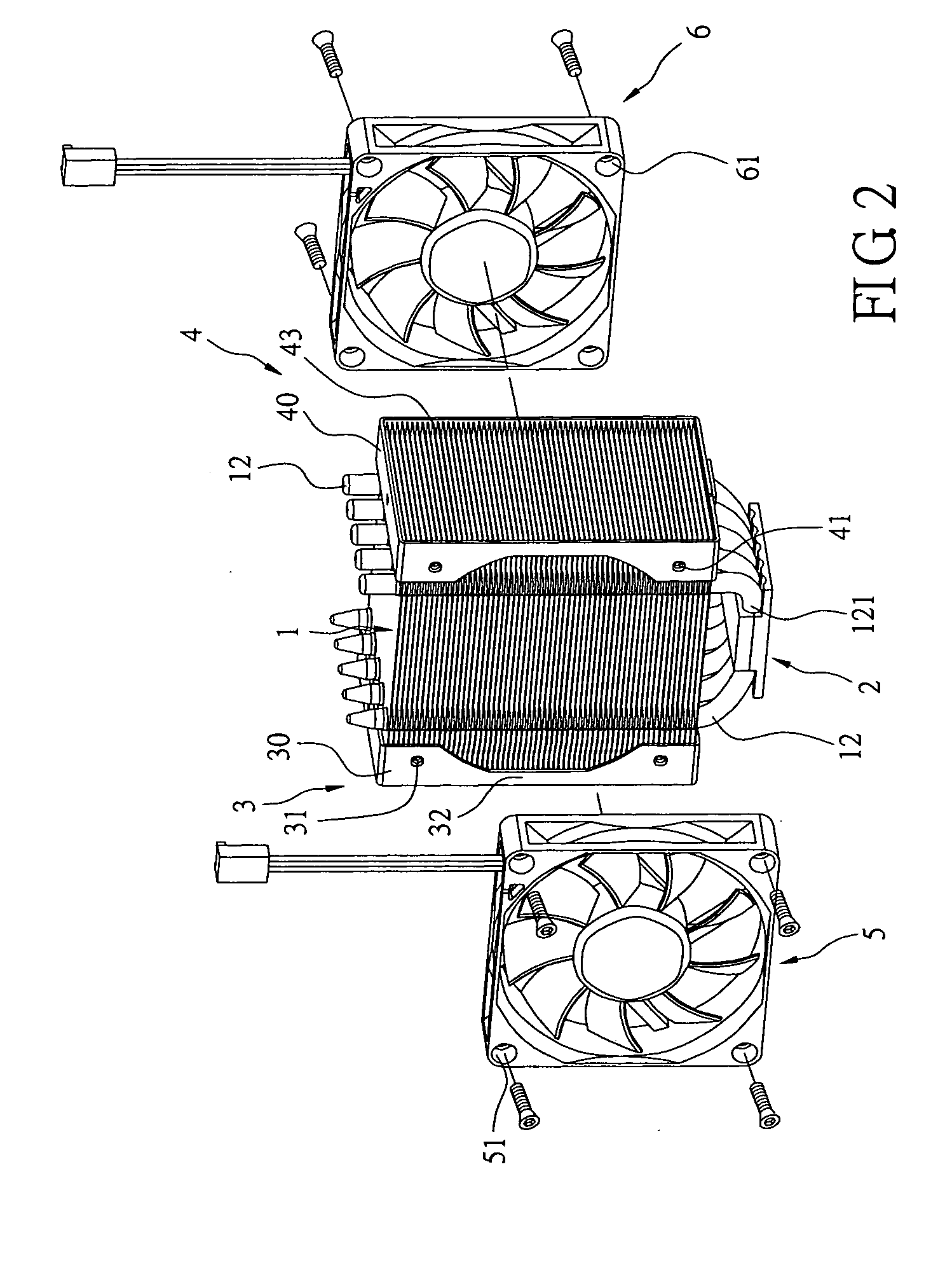
[0014] Reference is made to FIGS. 1-5. The present invention provides a heat dissipation module with a pair of fans, including a fin group 1, first and second supporting mechanisms 3, 4 and first and second fans 5, 6.

[0015] The fin group 1 includes a plurality of heat dissipation fins 11 in a stack, a plurality of heat pipes 12 in a U-shape, and a heat board 2. Each heat pipe 12 has two free terminals 12a, 12b stretching in the same direction. The heat pipe 12 also has a non-enveloped portion 121 between two free terminals 12a, 12b. The two free terminals of the heat pipe 12 penetrate through each heat dissipation fin 11 of the fin group 1 in the same direction to allocate each heat dissipation fin 11. The heat board 2 is located at the non-enveloped portion 121 of the each heat pipe 12. Therefore, heat produced by electrical device can be to the heat board, into the heat pipe, into the fins and eventually dissipated to the surrounding environment.

[0016] The heat board 2 can take ...


PUM


Abstract

A heat dissipation module with a pair of fans is described. The heat dissipation module has a heat dissipation fin, a heat pipe and a pair of fans. The present invention enhances heat dissipation efficiency. The present invention has a fin group having a plurality of heat dissipation fins in stack. A first and a second supporting mechanism with a plurality of threaded holes are set on opposite sides of the fin group. A first and a second fans are individually set on opposite sides of the fin group. Each of the first and the second fans has holes corresponding to the threaded holes of the first and the second supporting mechanism. Therefore, the first and the second fans can be built at opposite sides by using the first and the second supporting mechanism.

Description

FIELD OF THE INVENTION [0001] The present invention relates to a heat dissipation module with a pair of fans, and especially to a module with a pair of fans on opposite sides of the fin group. The two fans are set to blow air in the same direction, and the present invention can suck in cold air and blow out hot air to increase convection, thereby enhancing the efficiency of heat dissipation. BACKGROUND OF THE INVENTION [0002] With advances in electronic engineering, electrical products produce much more heat. Due to the closed casing of the electrical products, heat dissipation is also more difficult than before dissipation successfully and efficiently can help electrical products have a higher performance. Therefore, the dissipation system is increasingly important. Usually, a designer produces a heat dissipation system with a larger area at the surface of the products to be dissipated. [0003] However, the dissipating devices are not modularized, so the fans are not easily set on t...

Claims


Application Information

Patent Timeline
IPC IPC(8): H01L23/427H01L23/467
CPCH01L23/427H01L23/467H01L2924/0002H01L2924/00F28D15/0275
Inventor ZHANG, JIEZHANG, MIN
Owner MOLEX INC
Why Eureka
Try Eureka