
Assembly plant for assembling industrial products

a technology for assembling industrial products and assembly sequences, applied in the direction of charging manipulation, lighting and heating apparatus, furniture, etc., can solve the problems of restricting flexibility with respect to changes in assembly sequences and integration of different automotive concepts, and achieve the effect of simplifying structural complexity

Inactive Publication Date: 2005-04-28
BAYERISCHE MOTOREN WERKE AG
View PDF11 Cites 14 Cited by
  • Summary
  • Abstract
  • Description
  • Claims
  • Application Information

AI Technical Summary

Benefits of technology

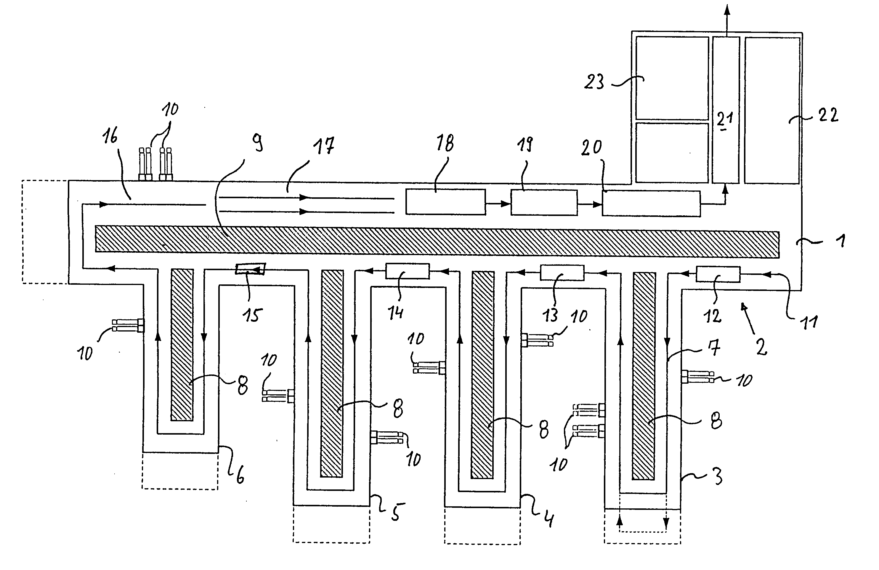
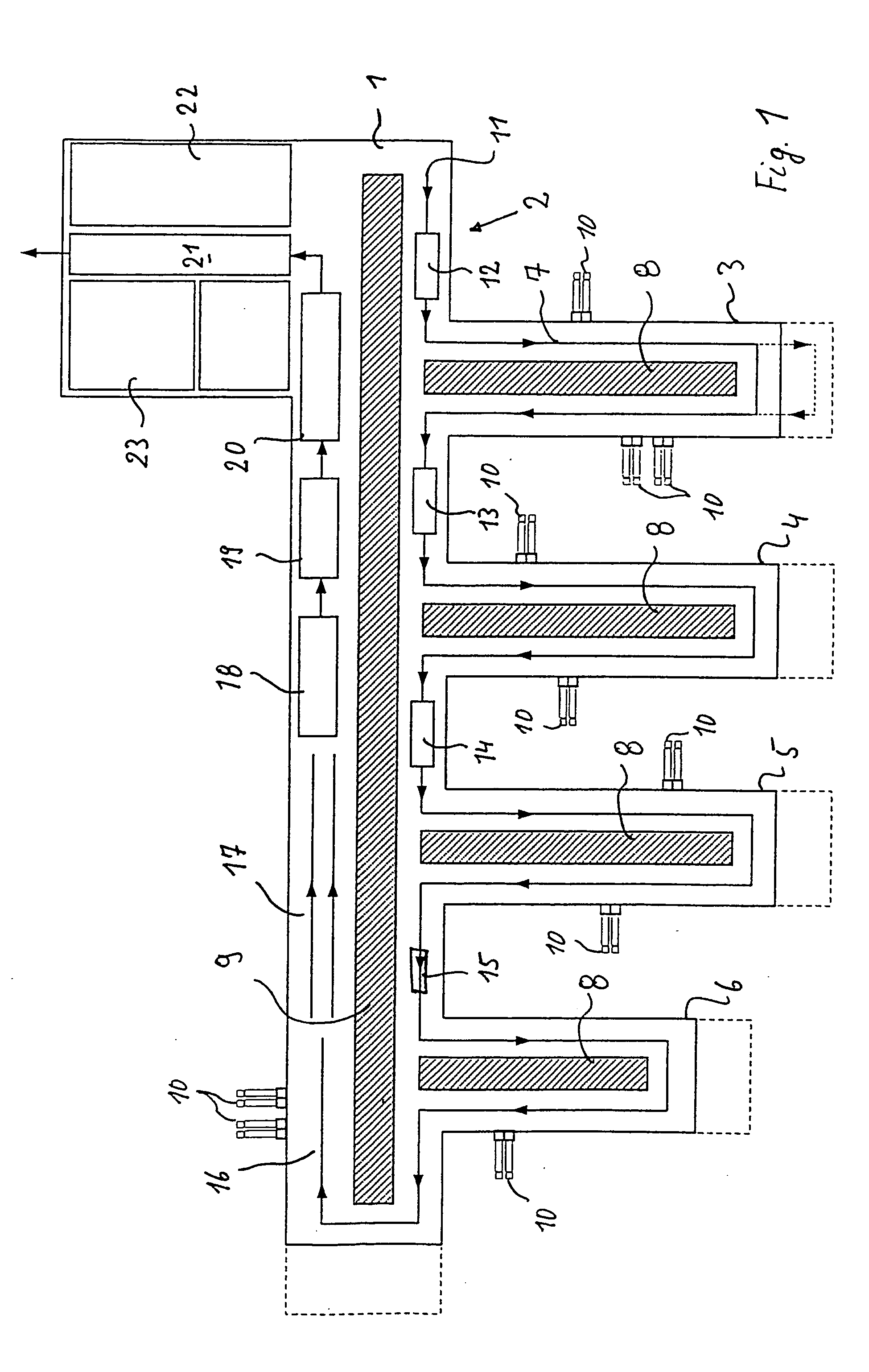
[0006] This object is achieved by a central elongated assembly hall provided with finger-like hall extensions branching off from it on a longitudinal side. The conveyor devices run on the longitudinal sides of the central assembly hall and on the outer sides of the hall extensions so that a U-shaped path is obtained on the whole. Thus at least one transverse side of the hall is free and is available for design changes, lengthening the hall and thus also the conveyor path without making far-reaching changes in the overall sequence.
[0009] The refinement of the invention, in which supply lines for nearby assembly lines are arranged above the work rooms and / or social rooms, simplifies the structural complexity, also with respect to a simple expansion of the assembly halls.
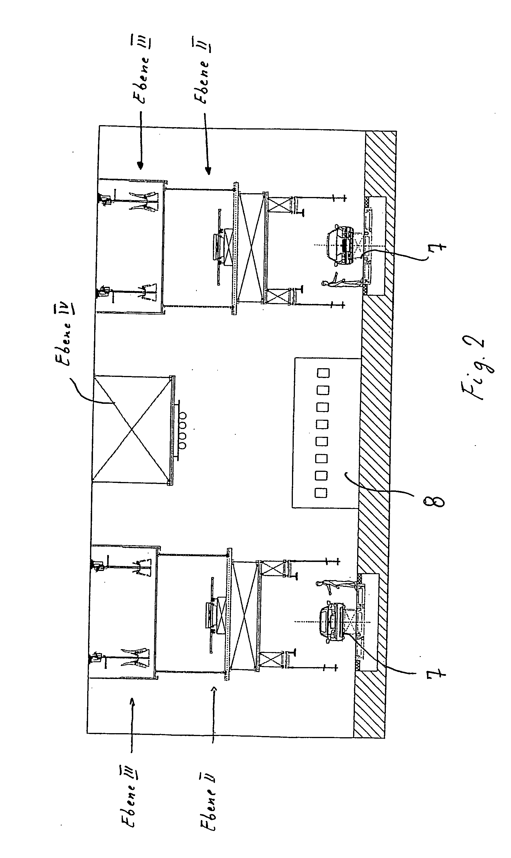
[0016] The return conveyance of the individual conveyor components such as transport carriages, assembly equipment carriers and the like is accomplished in a second level II (FIG. 2) above the conveyor system. The components to be assembled at the assembly sites are supplied via a separate conveyor system which is situated in its own third level III (FIG. 2) above the second level. This prevents a mutual blockade of the individual conveyor systems. Renovation measures can thus be implemented largely independently of one another, within a short period of time and with a low investment cost.

Problems solved by technology

One disadvantage of this basic concept of final assembly for vehicles is its restricted flexibility with respect to changes in assembly sequences and integration of different automotive concepts.

Method used


Image

  • Assembly plant for assembling industrial products
  • Assembly plant for assembling industrial products
  • Assembly plant for assembling industrial products

Examples


Embodiment Construction

[0014]FIG. 1 shows a schematic diagram of a central assembly hall 1 for the final assembly of motor vehicles, in particular passenger vehicles. In this example, four finger-like hall extensions 3, 4, 5 and 6 are added onto a long side 2 of this assembly hall 1.

[0015] The conveyor system 7 runs in a U shape on the outer sides of the assembly hall 1 and the hall extensions 3 through 6. This shows the conveyor system 7 as a single conveyor installation. In practice, however, it consists of multiple conveyor installations, which may be expanded as needed.

[0016] The return conveyance of the individual conveyor components such as transport carriages, assembly equipment carriers and the like is accomplished in a second level II (FIG. 2) above the conveyor system. The components to be assembled at the assembly sites are supplied via a separate conveyor system which is situated in its own third level III (FIG. 2) above the second level. This prevents a mutual blockade of the individual con...


PUM


Abstract

An assembly plant, in particular for assembling motor vehicles, which permits design of final assembly of motor vehicles so that it is as flexible as possible in terms of space. A central elongated assembly hall is provided in which essentially automated assembly regions are provided and finger-like partial regions having essentially manual workplaces are provided projecting at a right angle from the longitudinal side. A change in the sequence in the manual regions can be accomplished easily by means of an extension of the finger-like partial regions at the head end.

Description

[0001] This application claims the priority of German application no. 10208850.0, filed Mar. 1, 2002, and PCT International Patent Application No. PCT / EP03 / 01401, filed Feb. 13, 2003, the disclosure of which is expressly incorporated by reference herein. BACKGROUND AND SUMMARY OF THE INVENTION [0002] This invention relates to an assembly plant for assembling industrial products, and in particular vehicles. [0003] A generic assembly plant is known from European Patent EP 0 738 652 B1. It has a central area with hall areas branching off from it radially or in a cross-shaped configuration with U-shaped conveyor loops in each hall area. Other separate assembly plants are provided in the intermediate spaces, where modules can be preassembled. Short conveyance pathways for the preassembled modules can be achieved with this arrangement. [0004] One disadvantage of this basic concept of final assembly for vehicles is its restricted flexibility with respect to changes in assembly sequences an...

Claims


Application Information

Patent Timeline
Patent Type & Authority Applications(United States)
IPC IPC(8): B23P21/00B62D65/00B62D65/02B62D65/18
CPCB23P21/004B62D65/18B62D65/00B23P2700/50
Inventor FENZL, WERNERSCHLAGE, GERDKNAU, JAN
Owner BAYERISCHE MOTOREN WERKE AG
Learn More