X-ray imaging device

a technology of x-ray imaging and dose detection, which is applied in the direction of radiation controlled devices, optical radiation measurement, instruments, etc., can solve the problems of low accuracy in detecting x-ray dosage, no description regarding the manner of x-ray dosage detectors, and adversely affecting image detection

Active Publication Date: 2005-04-28
FUJIFILM CORP +1
View PDF7 Cites 7 Cited by
  • Summary
  • Abstract
  • Description
  • Claims
  • Application Information

AI Technical Summary

Benefits of technology

[0013] The present invention has been developed in view of the above circumstances. It is an object of the present invention to provide an X-ray imaging device that employs a solid state detector as an X-ray image detecting means, and improves the accuracy in detecting X-ray dosages, to be applied toward controlling irradiated dosages of X-rays, without adversely affecting detection of an image by the solid state detector.

Problems solved by technology

However, if the X-ray dosage detector is provided on the rear side of the solid state detector, the accuracy in detection of the X-ray dosage is low.
However, low energy components are largely absorbed by the solid state detector, thereby changing the spectrum balance of the X-rays detected by the X-ray dosage detector.
However, there is no description regarding what manner of X-ray dosage detector is employed.
However, the X-ray dosage detector is constituted by a fluorescent plate, a light collecting field, a light transmitting plate, and a light shielding plate, causing the structure to be complex, and limiting the degree to which the detector can be made thin.
Therefore, the distance between a subject and the film for detecting an X-ray image of the subject cannot be made short, thereby decreasing the resolution of the X-ray image.

Method used


Image

  • X-ray imaging device
  • X-ray imaging device
  • X-ray imaging device

Examples


Embodiment Construction

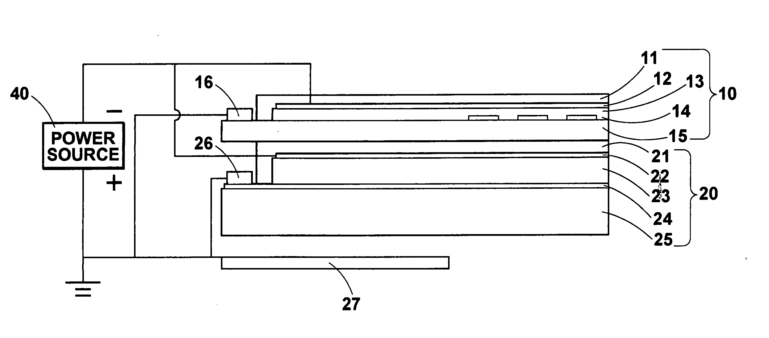
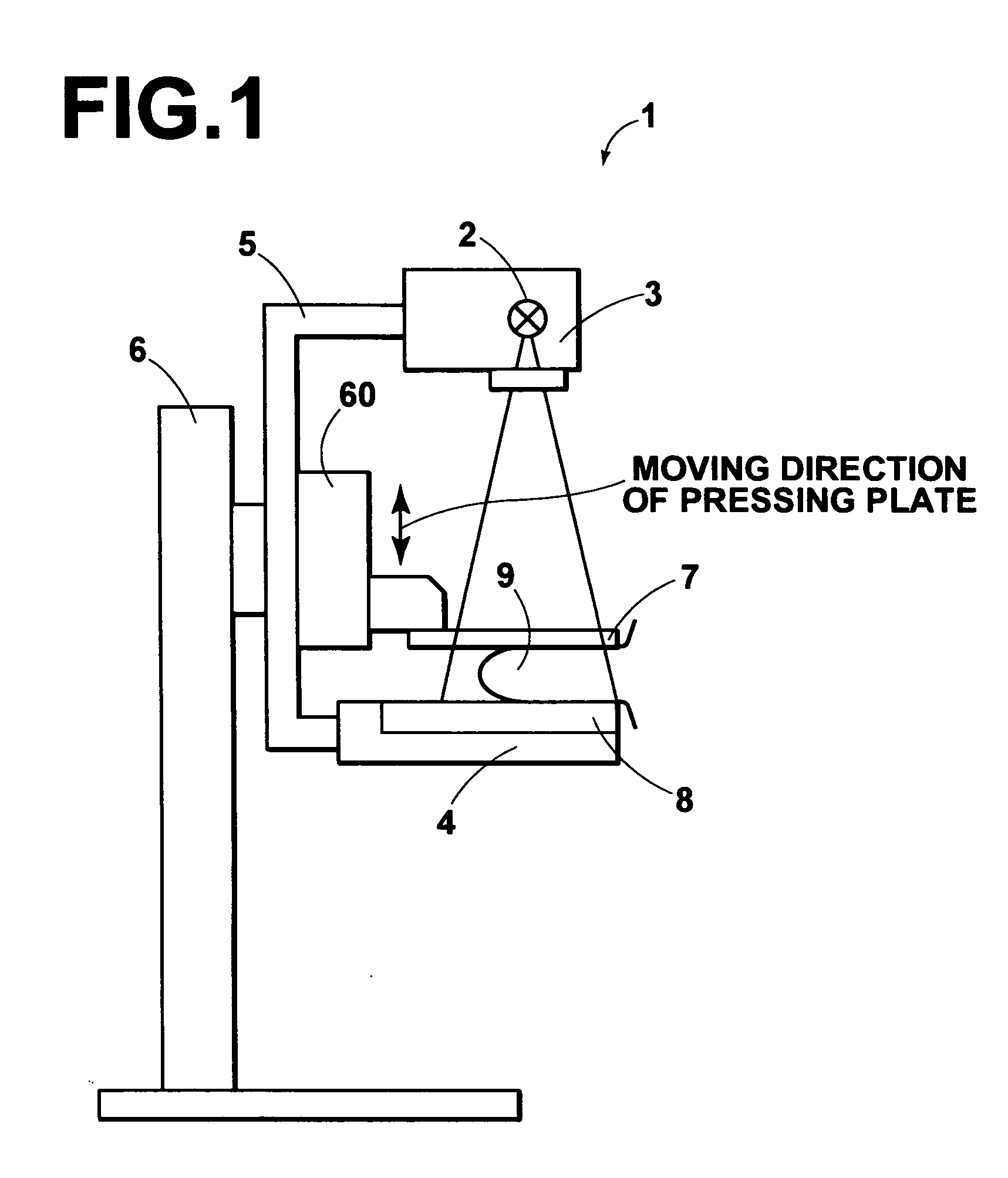
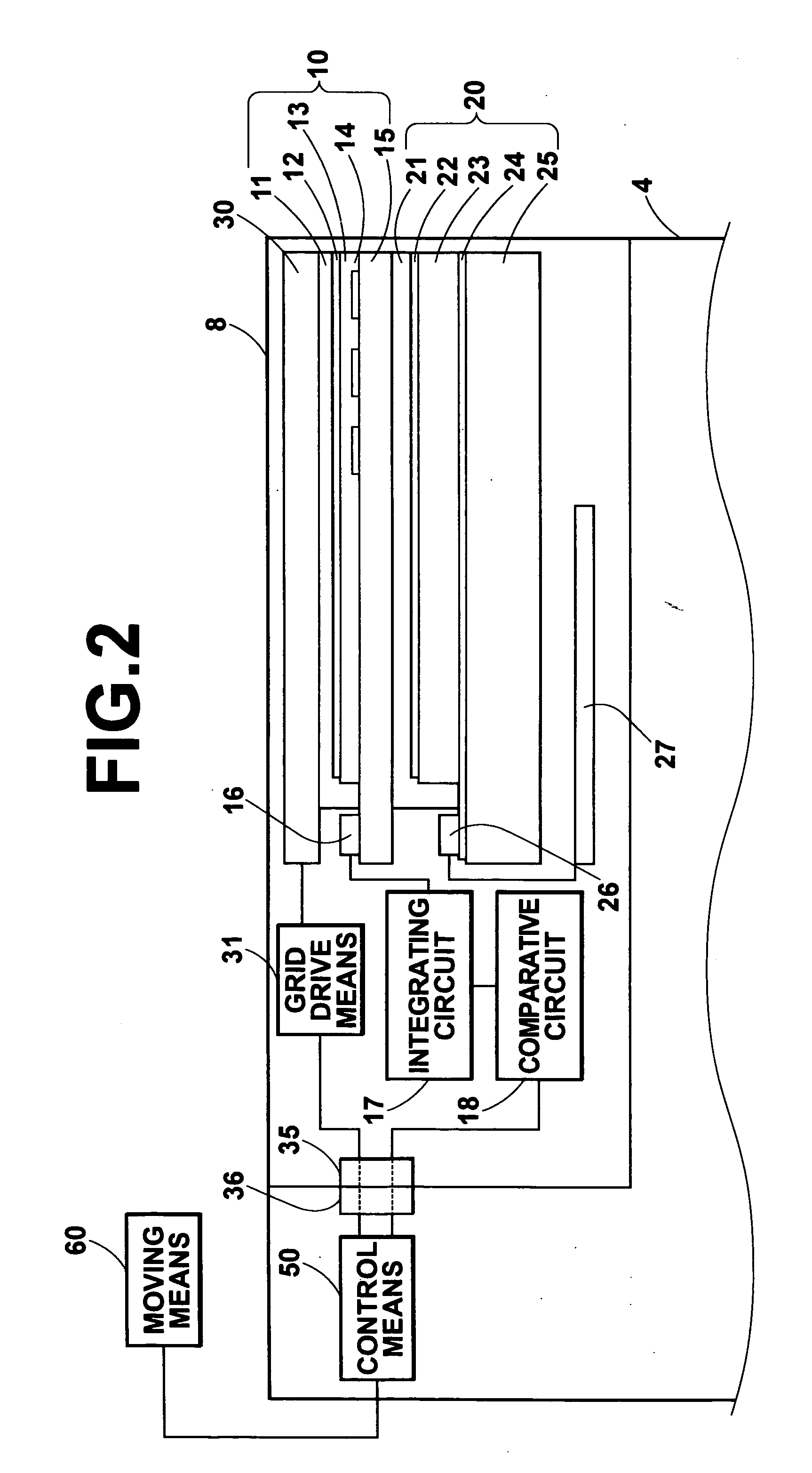
[0042] Hereinafter, an embodiment of the present invention will be described in detail with reference to the attached drawings. FIG. 1 is a schematic diagram illustrating an example of a mammography apparatus, to which the X-ray imaging device according to the present invention is applied. FIG. 2 is a schematic diagram illustrating the interior of a film cassette of the mammography apparatus. FIG. 3 is a schematic diagram illustrating the manner in which a power source is connected within the film cassette. FIG. 4 is a schematic diagram illustrating a conductive layer portion of an X-ray dosage detector of the mammography apparatus. FIG. 5 is a circuit diagram illustrating an integrating circuit and a comparative circuit of the mammography apparatus.

[0043] A mammography apparatus 1 comprises: an X-ray source housing portion 3 that houses an X-ray source 2 within its interior; an imaging table 4 for holding a film cassette 8, which is an X-ray imaging device; arms 5; and a base 6. T...


PUM


Abstract

An X-ray imaging device is equipped with a solid state detector, for recording image information by being irradiated with X-rays that bear image information and for outputting image signals that represent the recorded image information, and an X-ray dosage detector for detecting the dosage of irradiated X-rays. The X-ray dosage detector is provided between an X-ray source and the solid state detector, thereby enabling accurate measurement of the X-ray dosage, without being influenced by the solid state detector. In addition, the X-ray dosage detector is equipped with a photoconductive layer. Therefore, the X-ray dosage detector can be made thinner than conventional X-ray dosage detectors, which are constituted by a fluorescent plate, a light collecting field, a light transmitting plate, and a light shielding plate. Accordingly, decreases in resolution of images detected by the solid state detector can be prevented.

Description

BACKGROUND OF THE INVENTION [0001] 1. Field of the Invention [0002] The present invention relates to an X-ray imaging device that obtains an X-ray image of a subject, by detecting X-rays that have passed through the subject. [0003] 2. Description of the Related Art [0004] Presently, various X-ray imaging apparatuses, for obtaining X-ray images to be utilized for medical diagnoses, have been proposed and are in practical use. These X-ray imaging apparatuses employ solid state detectors (having semiconductors as main components thereof) as X-ray image detecting means. The solid state detectors detect X-rays that have passed through subjects, and obtain image signals that represent X-ray images of the subject. [0005] A variety of formats have been proposed for the solid state detectors to be utilized in these apparatuses. Regarding a charge generating process for converting X-rays to electrical charges, there is a photo conversion type of solid state detector, and a direct conversion t...

Claims


Application Information

Patent Timeline
Patent Type & Authority Applications(United States)
IPC IPC(8): G01T1/00A61B6/00G01T1/24G03B42/02H04N5/32
CPCA61B6/502A61B6/542A61B6/4291H04N5/32A61B6/585
Inventor SHOJI, TAKASHI
Owner FUJIFILM CORP
Why Eureka
Try Eureka