
Receiver circuit, interface circuit, and electronic instrument

a technology of interface circuits and receivers, applied in the direction of instruments, baseband system details, pulse techniques, etc., can solve the problems of inability to perform data transfer and limited power consumption

Inactive Publication Date: 2005-04-28
138 EAST LCD ADVANCEMENTS LTD
View PDF8 Cites 28 Cited by
  • Summary
  • Abstract
  • Description
  • Claims
  • Application Information

AI Technical Summary

Problems solved by technology

However, since the high-speed serial transfer interface allows current to constantly flow through the transmitter circuit and the receiver circuit, a reduction of power consumption is limited.
On the other hand, data transfer cannot be performed if the path of the constant current is cut.

Method used


Image

  • Receiver circuit, interface circuit, and electronic instrument
  • Receiver circuit, interface circuit, and electronic instrument
  • Receiver circuit, interface circuit, and electronic instrument

Examples


Embodiment Construction

[0026] Embodiments of the present invention are described below.

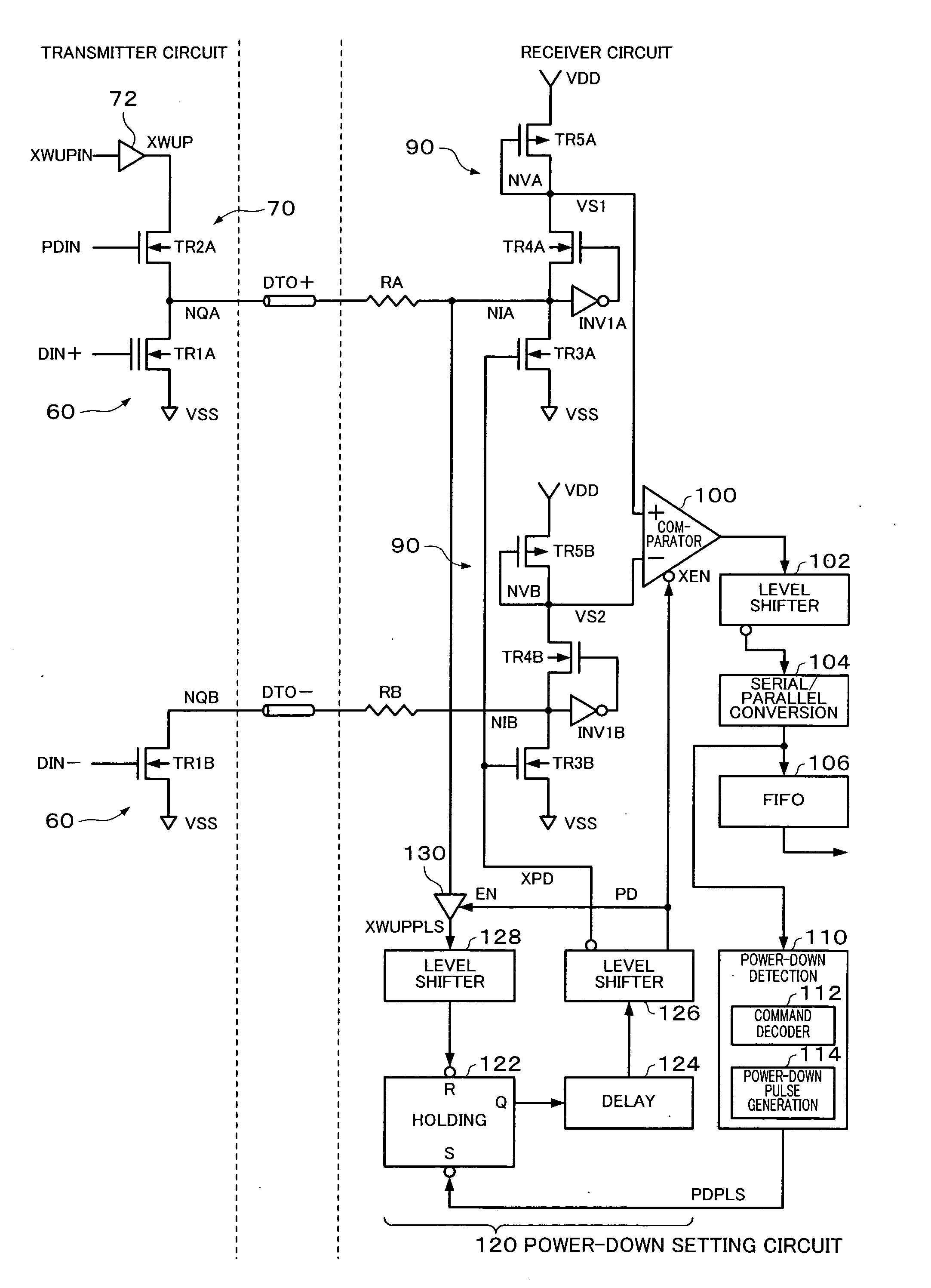
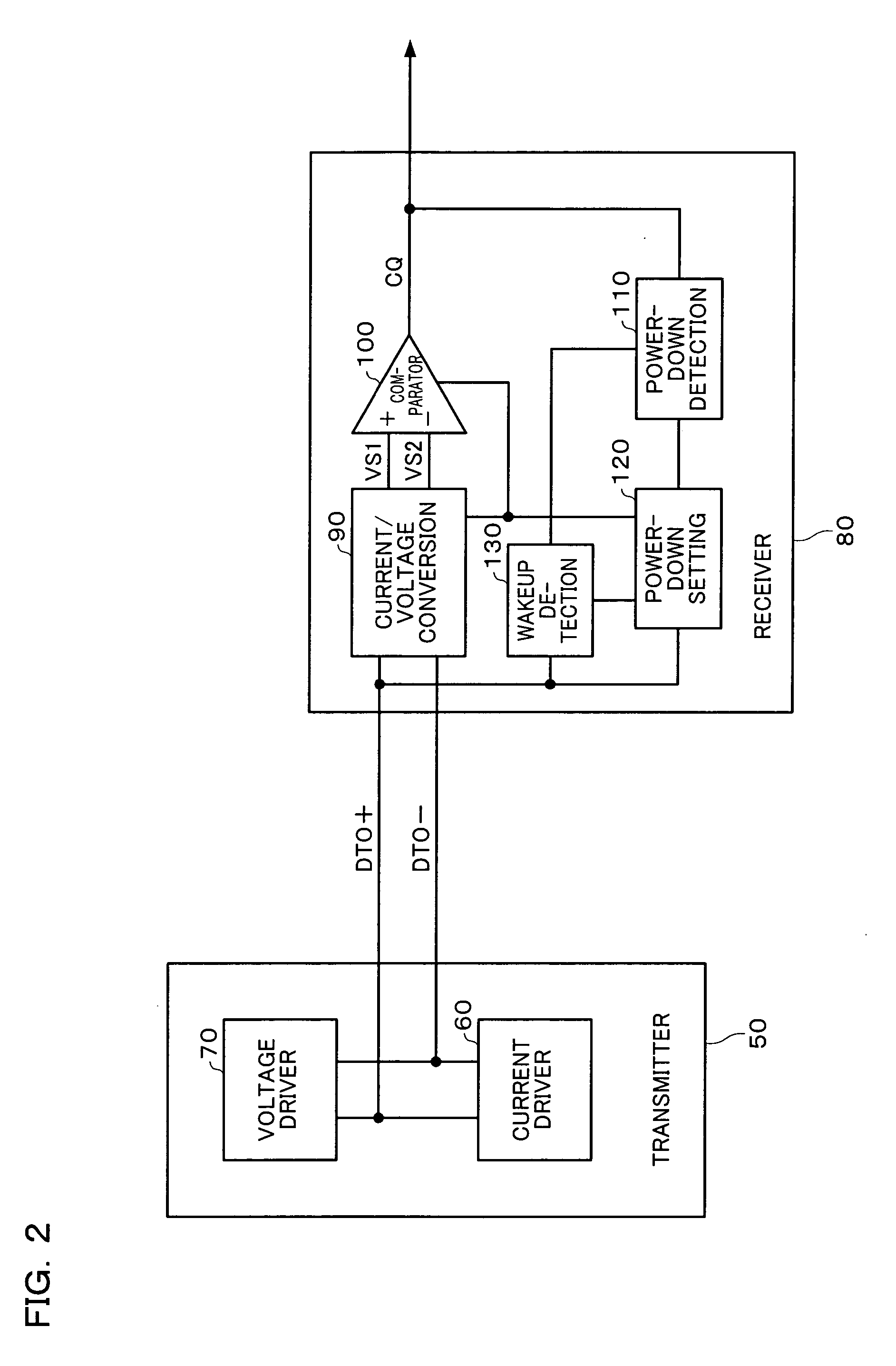
[0027] One embodiment of the present invention provides a receiver circuit connected with a transmitter circuit which current-drives differential signal lines through the differential signal lines, the receiver circuit comprising: [0028] a current / voltage conversion circuit which performs a current / voltage conversion based on current which flows through the differential signal lines and outputs first and second voltage signals which form differential voltage signals; [0029] a comparator which compares the first and second voltage signals and outputs an output signal; [0030] a power-down detection circuit which, when the transmitter circuit transmits a power-down command by current-driving the differential signal lines in a normal transfer mode, detects the transmitted power-down command based on a comparison result from the comparator; and [0031] a power-down setting circuit which sets at least one of the current / volta...


PUM


Abstract

A receiver circuit includes: a current / voltage conversion circuit which performs a current / voltage conversion based on current which flows through the differential signal lines and outputs voltage signals; a comparator which compares the voltage signals and outputs an output signal; a power-down detection circuit which, when the transmitter circuit transmits a power-down command by current-driving the differential signal lines in a normal transfer mode, detects the transmitted power-down command based on a comparison result from the comparator; and a power-down setting circuit which sets at least one of the current / voltage conversion circuit and the comparator to a power-down mode when the power-down command is detected.

Description

[0001] Japanese Patent Application No. 2003-314055, filed on Sep. 5, 2003, Japanese Patent Application No. 2004-14412, filed on Jan. 22, 2004, and Japanese Patent Application No. 2004-65938, filed on Mar. 9, 2004, are hereby incorporated by reference in their entireties. BACKGROUND OF THE INVENTION [0002] The present invention relates to a receiver circuit, an interface circuit, and an electronic instrument. [0003] In recent years, a high-speed serial transfer interface such as low voltage differential signaling (LVDS) has attracted attention as an interface standard aiming at reducing EMI noise or the like. In the high-speed serial transfer interface, data transfer is realized by allowing a transmitter circuit to transmit serialized data using differential signals and a receiver circuit to differentially amplify the differential signals. Japanese Patent Application Laid-open No. 2002-314397 has disclosed a conventional technology relating to the high-speed serial transfer interface...

Claims


Application Information

Patent Timeline
Patent Type & Authority Applications(United States)
IPC IPC(8): H03K19/00H03K19/0175G06F3/00H03L5/00H04B1/16H04L25/02H04L25/45
CPCH04L25/45H04L25/0292H04L12/02H03K19/00H04L25/40H04L69/32
Inventor SHIBATA, YUKINARISAITO, NOBUYUKIHASEGAWA, TOMONAGAISHIDA, TAKUYA
Owner 138 EAST LCD ADVANCEMENTS LTD
Features
  • Generate Ideas
  • Intellectual Property
  • Life Sciences
  • Materials
  • Tech Scout
  • Unparalleled Data Quality
  • Higher Quality Content
  • 60% Fewer Hallucinations
Learn More