Identification apparatus

Inactive Publication Date: 2005-04-28
MOBILE ASPECTS INC
View PDF6 Cites 33 Cited by
  • Summary
  • Abstract
  • Description
  • Claims
  • Application Information

AI Technical Summary

Benefits of technology

[0008] It is, therefore, an object of the present invention to provide an identification apparatus that overcomes the deficiencies of the prior art. It is another object of the present invention to provide an identification apparatus that is useful in identifying stationary objects. It is a still further object of the present invention to provide an identification apparatus that is able to receive information from an object regardless of its position. It is yet another object of the present invention to provide an identification apparatus that does not require multiple antennae. It is still another object of the present invention to provide an identification apparatus that is more easily tunable than prior art systems.

Problems solved by technology

However, problems arise when the tagged objects are static or stationary.
In these situations, the object, and therefore the tag, may be positioned in an orientation that is unfavorable or detrimental to the RF / ID powering and communicating process.
These inappropriately oriented tags have a low probability of being identified by the reader or antenna, which causes errors and other malfunctions in the system.
While such a multiple antenna system has solved certain drawbacks, such a system also has numerous limitations.
Such positions will not guarantee that a tag will be in an operable powering / communicating position.
Second, the increased number of antennae will require a complicated and sophisticated controller for switching the location of the powering / communicating antenna.
In addition, such multiple-antennae systems are more complicated and require a more sophisticated controller and electronics.
Multi-antenna systems also require more complicated and extensive tuning, since each antenna in the system must be tuned using a matching circuit.
Increased number of antennae will require more tuning circuits and the large number of antennae in close proximity may make it difficult to tune, which may require each tuning board to have different value components.

Method used


Image

  • Identification apparatus
  • Identification apparatus
  • Identification apparatus

Examples


Embodiment Construction

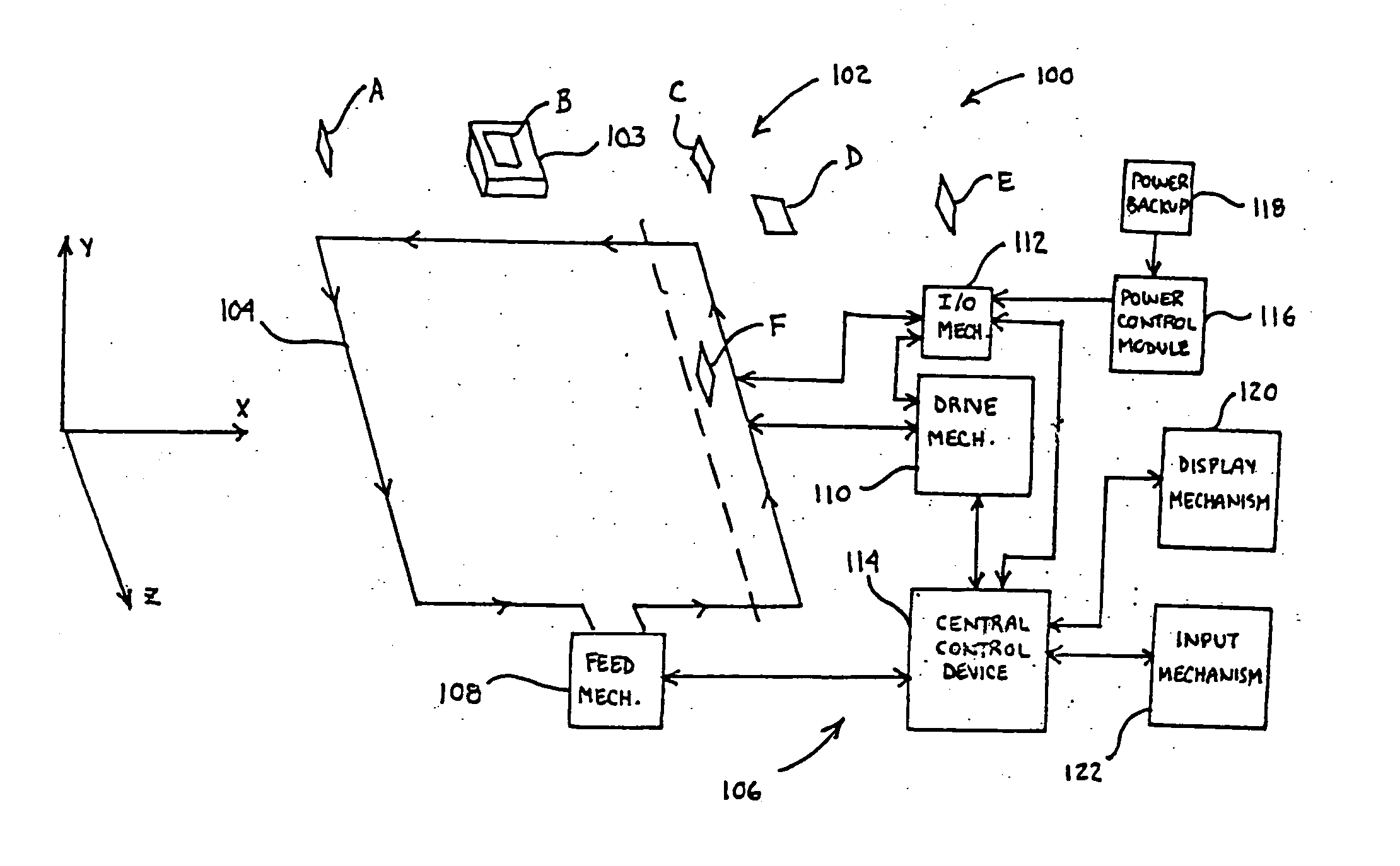
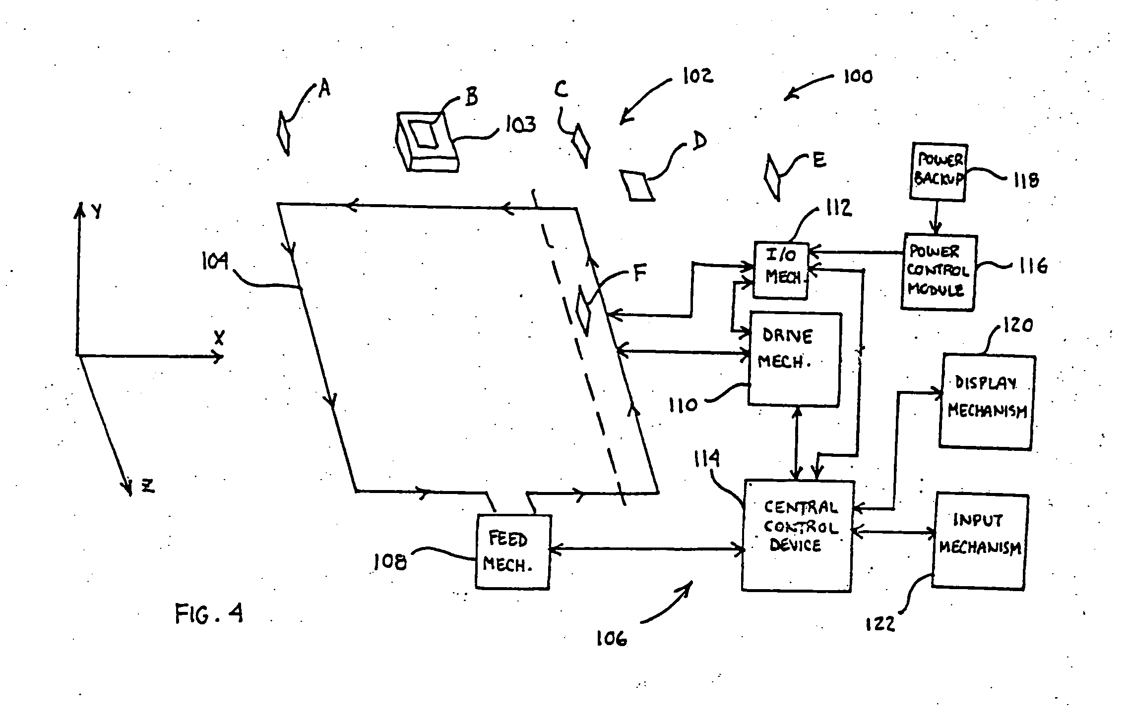
[0016] For purposes of the description hereinafter, the terms “upper”, “lower”, “right”, “left”, “vertical”, “horizontal”, “top”, “bottom” and derivatives thereof shall relate to the invention as it is oriented in the drawing figures. However, it is to be understood that the invention may assume various alternative variations and step sequences, except where expressly specified to the contrary. It is also to be understood that the specific devices and processes illustrated in the attached drawings, and described in the following specification, are simply exemplary embodiments of the invention. Hence, specific dimensions and other physical characteristics related to the embodiments disclosed herein are not to be considered as limiting.

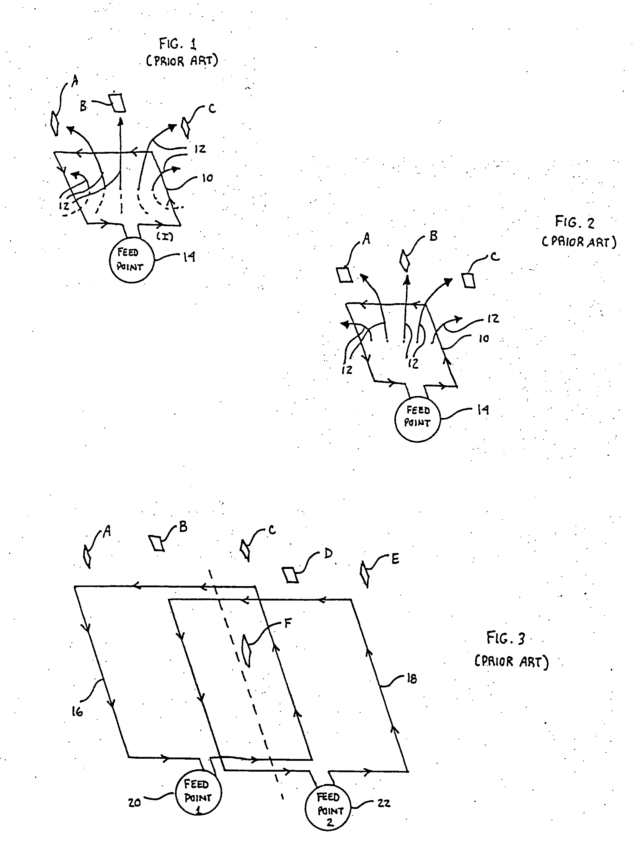
[0017] According to the prior art, as illustrated in FIGS. 1 and 2, an antenna 10 is used to project signals 12 that communicate with and power tags A, B and C. Current (I) is directed through the antenna 10 via a feed point 14. Further, the antenna 10...


PUM


Abstract

Disclosed is an identification apparatus for use in connection with multiple discrete identity source elements positioned in an identification apparatus signal identification area. The identification apparatus includes at least one signal receiving mechanism for receiving a signal emitted from the identity source elements. The signal receiving mechanism has a field of detection of at least a portion of the identification apparatus signal identification area. Further, the signal receiving mechanism is capable of moving along an axis of movement. A control mechanism is in communication with the signal receiving mechanism. Further, the control mechanism can control the movement of the signal receiving mechanism along the axis of movement and / or receive, process and transmit the signal received by the signal receiving mechanism. A method of receiving a signal from identity source elements positioned in a single identification area is also disclosed.

Description

BACKGROUND OF THE INVENTION [0001] 1. Field of the Invention [0002] The present invention relates generally to identification apparatus and devices for gathering data regarding a plurality of objects or items and, in particular, to an identification apparatus that is useful in identifying stationary objects, items, tags and the like regardless of orientation. [0003] 2. Description of Related Art [0004] In order to track and gather data regarding objects, such as items, products, individuals, cars, etc., radio frequency (RF) identification technology allows for the accurate tracking of the objects in the system. Typically, the object or objects will have an identification source or tag associated therewith, and this tag provides a unique identification to the object or individual. A receiving unit, typically in the form of an antenna, interacts with the tags and receives signals for further processing. After the signal is received, a control mechanism or other device processes the si...

Claims


Application Information

Patent Timeline
IPC IPC(8): G06K7/08G08B13/14
CPCG06K7/10336
Inventor GREENE, CHARLESRAHIM, MUHAMMAD
Owner MOBILE ASPECTS INC
Why Eureka
Try Eureka