
Display device and telecommunication system

a display device and telecommunication system technology, applied in the field of display devices and telecommunication systems, can solve the problems of user's movement restriction, user's view interruption, and difficulty in taking advantage of the display device that ensures the free use of user's hands, so as to improve the usability of the display device, facilitate the inspection of objects, and improve the usability

Inactive Publication Date: 2005-04-28
SEMICON ENERGY LAB CO LTD
View PDF71 Cites 85 Cited by
  • Summary
  • Abstract
  • Description
  • Claims
  • Application Information

AI Technical Summary

Benefits of technology

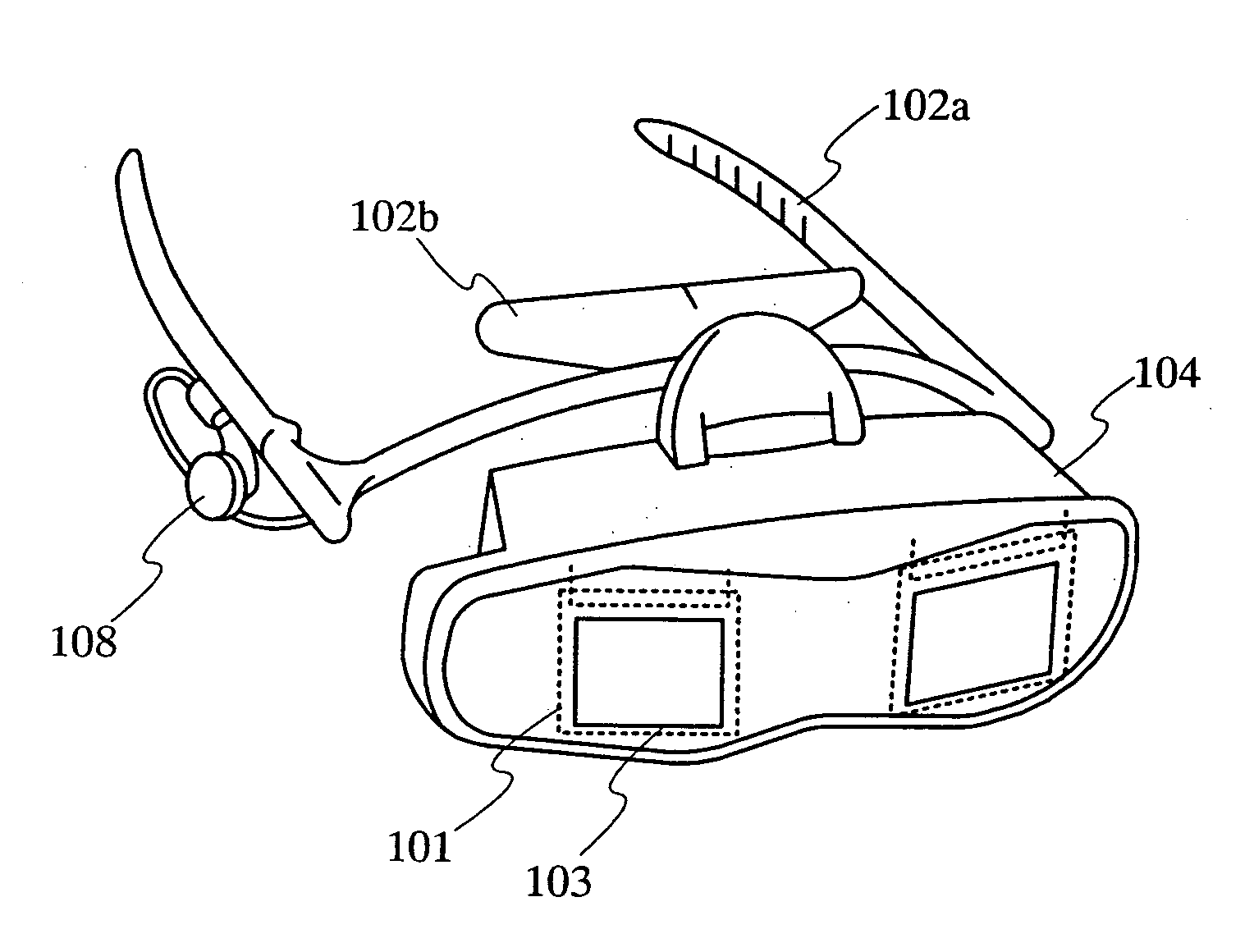
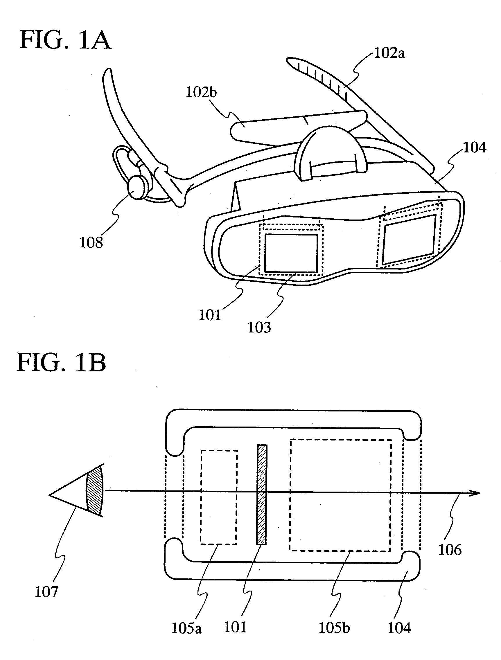
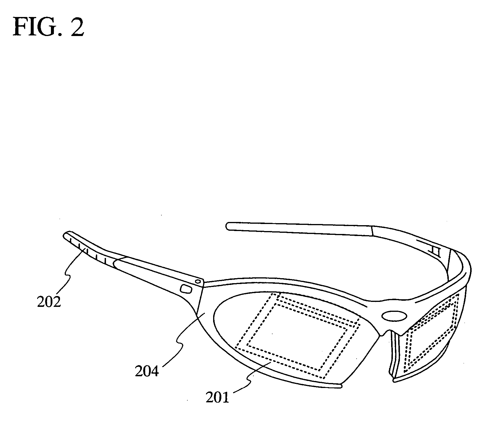
The invention provides a goggle display device that allows a user to see an image and their surrounding environment simultaneously without interfering with their view. This improves the user's usability and allows for the display device to be used in a navigation system. The device uses a light emitting device that can display an image and transmit light as a goggle display device, and includes an optical system that brings the light into focus on the retinas of the user. The device also allows for the display to be taken on / off frequently, making it easy to use. The invention also provides a telecommunication system that combines the goggle display device with a navigation system to provide additional visual information to the user.

Problems solved by technology

However, each of the aforementioned goggle display devices has a problem in that a user's view is interrupted by the use of the very device.
Therefore, the user's movement is restricted, which makes it difficult to take the advantage of the goggle display device that ensures the free use of user's hands.
Even in a goggle display device that directly writes an image to the retinas of a user, it is difficult for him to sense his surrounding scenery as light in the portion of the retinas to which an image is written.
Therefore, it is difficult for the user to see the surrounding scenery within his view in the area where the image is displayed.
Further, in the goggle display device that directly writes an image to the retinas of a user, a green laser diode, which is one of the three primary colors of light has not been put into practical use yet.
Therefore, it is difficult to display a full color image by this device.

Method used


Image

  • Display device and telecommunication system
  • Display device and telecommunication system
  • Display device and telecommunication system

Examples


embodiment 1

[Embodiment 1]

[0081] In this embodiment, specific configuration of on optical system used in the goggle display device of the invention is described.

[0082] An optical system used in the goggle display device of the invention is classified into a first optical system provided between a panel and an eyeball of a user, and a second optical system provided across the panel from the eyeball. FIG. 7 shows a positional relationship between an eyeball 701 of a user, a first optical system 702, a panel 703, and a second optical system 704 in the direction of a visual axis.

[0083] In FIG. 7, a convex lens 705 is used as the first optical system 702. In addition, two convex lenses 706 and 707 are used as the second optical system 704. The outside light entering the convex lens 706 passes through the convex lens 707, the panel 703, and the convex lens 705 in this order, and finally enters the eyeball 701. The convex lens 706 is focused on a point between the convex lens 706 and the convex lens...

embodiment 2

[Embodiment 2]

[0086] In this embodiment, one embodiment of the telecommunication system of the invention is described specifically.

[0087] In the case where the goggle display device of the invention has a means for detecting the direction in which the goggle display device faces, the directional information of the goggle display device itself can be obtained in addition to the positional information thereof. When the positional information and the directional information of the goggle display device are utilized in order to specify an area that is located in the direction in which the goggle display device faces, and check it with a database, information on the area such as the one on buildings within the area, the address of the area, and the like can be obtained.

[0088] It is assumed that a goggle display device 801 faces a certain direction at a specific point as shown in FIG. 8A. The goggle display device 801 calculates the positional information of the point such as the latitu...

embodiment 3

[Embodiment 3]

[0092] In this embodiment, more specific configuration of a light emitting device that is used in the goggle display device of the invention is described.

[0093]FIG. 9 shows one mode of a cross sectional view of a pixel in the light emitting device of the invention. In FIG. 9, TFTs 901 to 903 and light emitting elements 904 to 906 are formed over a substrate 900. The TFT 901 controls a current supply to the light emitting element 904. The TFT 902 controls a current supply to the light emitting element 905. Similarly, the TFT 903 controls a current supply to the light emitting element 906.

[0094] Reference numeral 907 denotes a light transmissive covering material for sealing the light emitting elements 904 to 906. The covering material 907 may be provided with a color filter.

[0095] The light emitting element 904 includes an anode 913 electrically connected to the TFT 901, an electroluminescent layer 914 formed on the anode 913, and a cathode 915 formed on the electrol...


PUM


Abstract

The invention provides a display device with which a user's view is not completely interrupted by an image that is displayed artificially and of which optical system is easy in design. In addition, the invention provides a telecommunication system capable of providing additional visual information by the use of the display device. According to the invention, an image can be displayed while securing a user's view by using a light emitting device that can display an image and transmit light as a display device. Specifically, a pair of electrodes included in a light emitting element is formed to transmit light so as to transmit the outside light. By crossing a visual axis of a user and a pixel portion of the light emitting device, both of the outside light and the light emitted from the pixel portion can enter into the eyeballs of a user.

Description

BACKGROUND OF THE INVENTION [0001] 1. Field of the Invention [0002] The present invention relates to a display device using light emitting elements, and to a telecommunication system using the display device. [0003] 2. Description of the Related Art [0004] A goggle display device has the characteristics of portability that enable the use of the device while it is worn by a user, and it has the advantage of providing visual information in any place without tying up user's hands. A goggle display device is sometimes called a face mounted display or a head mounted display. As for a goggle display device that is in practical use at present, there is the one that displays an image by using a liquid crystal display device (LCD). [0005] Besides the goggle display device using a liquid crystal display device, a goggle display device that can display an image by using a self-luminous light emitting device is proposed in recent years. A light emitting device using light emitting elements emit...

Claims


Application Information

Patent Timeline
Patent Type & Authority Applications(United States)
IPC IPC(8): G01C21/36G02B27/00G02B27/01G09G3/32H04N5/74
CPCG01C21/365G02B27/017G02B27/0172G02B2027/0112G02B2027/0132H04N5/7491G02B2027/0178G09G3/3225G09G2300/0842G09G2300/0861G09G2310/0251G02B2027/014
Inventor YAMAZAKI, SHUNPEIMIYAGAWA, KEISUKE
Owner SEMICON ENERGY LAB CO LTD
Learn More