Lighting device for photographing apparatus and photographing apparatus

a technology for photographing apparatus and light source, which is applied in the direction of exposure control, optical radiation measurement, instruments, etc., can solve the problems of difficult to confirm the composition of the image before, excessive electricity consumption, and the electric charge in the battery runs down almost immediately, so as to facilitate the composition confirmation and reduce the amount of electricity consumed

Inactive Publication Date: 2005-04-28
ASAHI KOGAKU KOGYO KK
View PDF3 Cites 48 Cited by
  • Summary
  • Abstract
  • Description
  • Claims
  • Application Information

AI Technical Summary

Benefits of technology

[0007] Therefore, an object of the present invention is to provide a lighting device, which can make it easy to confirm the composition of an image of an object before photographing when the object is in the dark, while the amount of electricity consumed is restrained.

Problems solved by technology

However, it is difficult to confirm the composition of the image before photographing the object when the object is in the dark, for example at night.
On the other hand, even if the lighting device intermittently radiates strobe light while forming a moving image, excess electricity is consumed and the electric charge in a battery runs down almost immediately.

Method used


Image

  • Lighting device for photographing apparatus and photographing apparatus
  • Lighting device for photographing apparatus and photographing apparatus
  • Lighting device for photographing apparatus and photographing apparatus

Examples


first embodiment

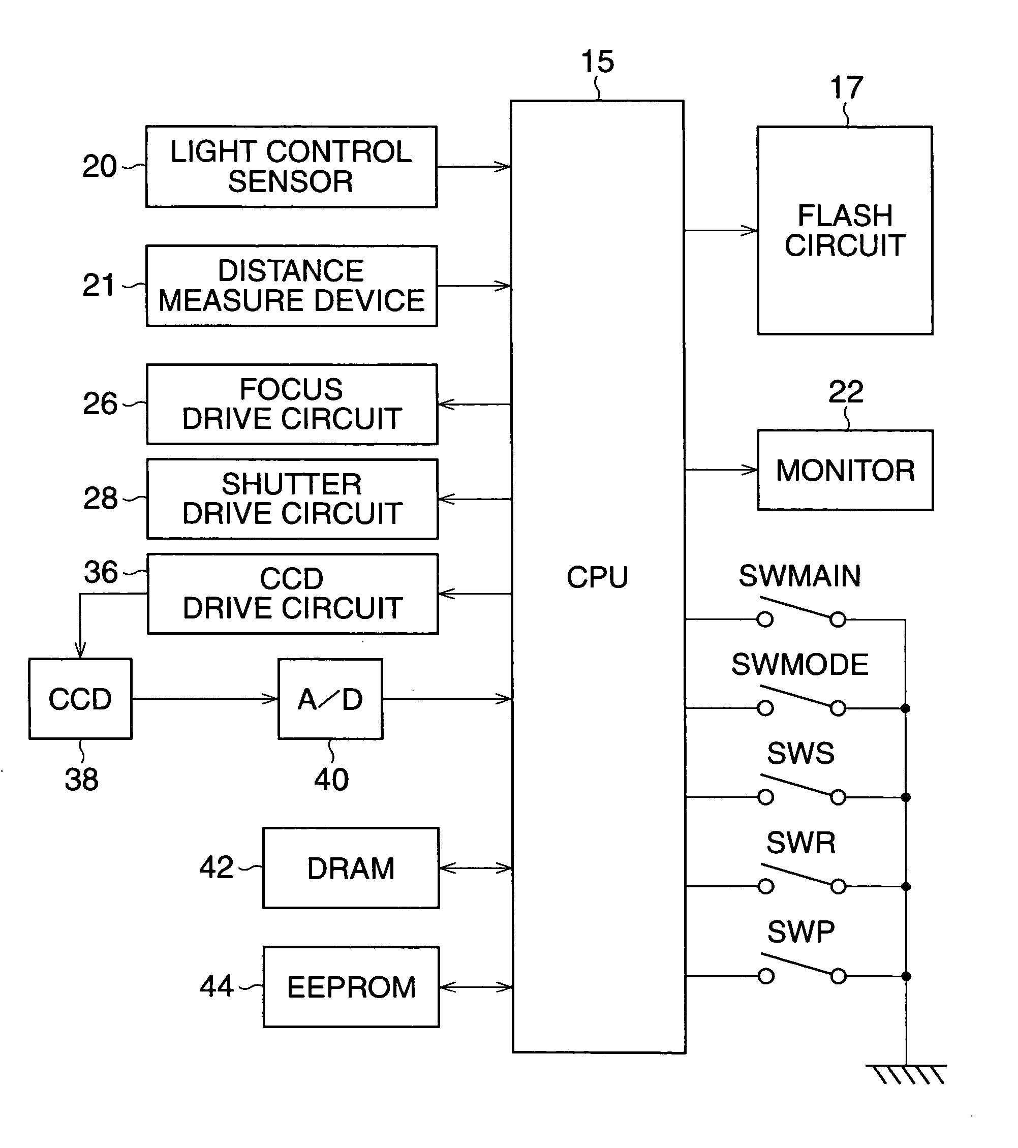
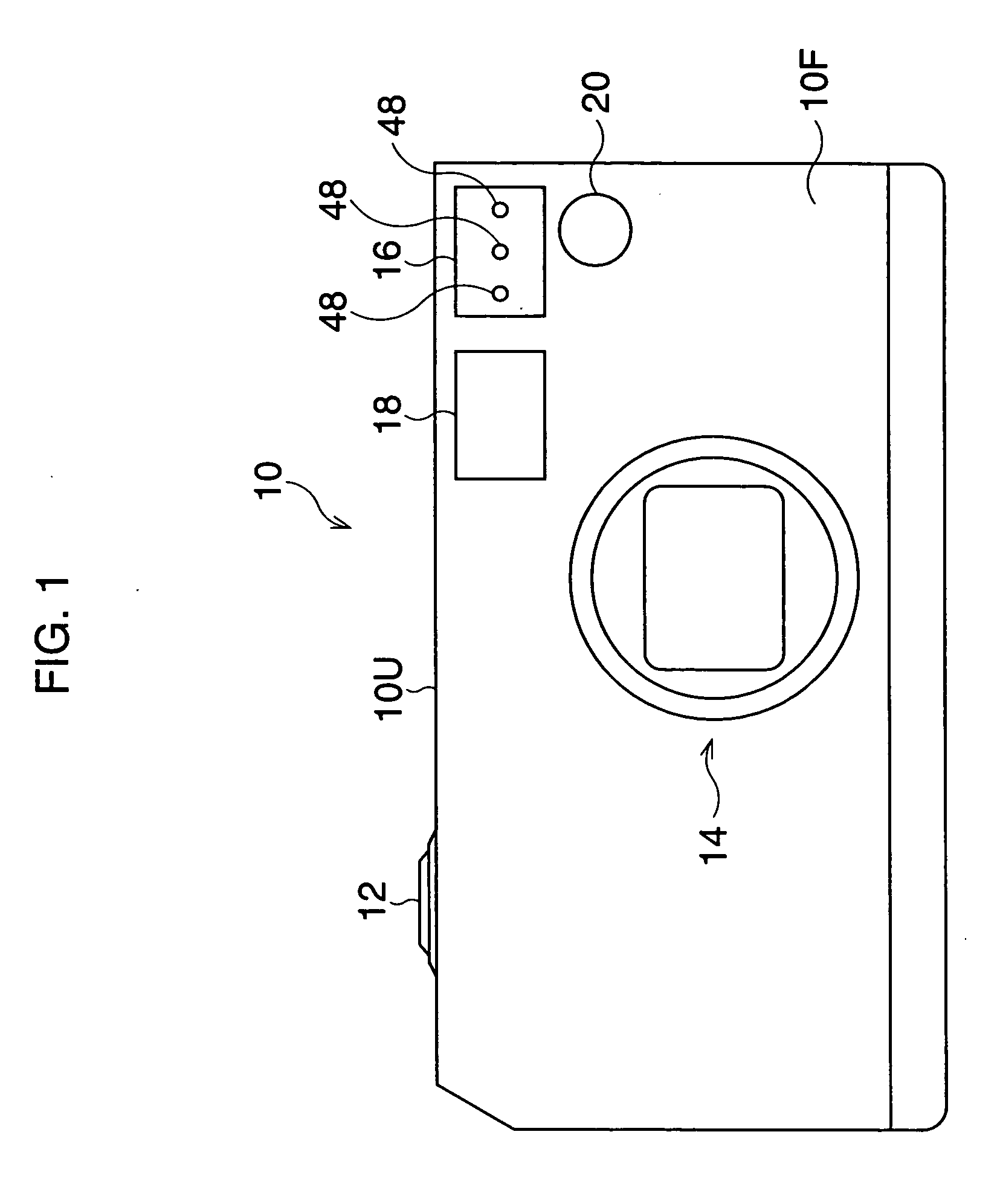
[0033]FIGS. 1 and 2 show the digital camera in the The digital camera 10 has an upper surface 10U, a front surface 10F, and a back surface 10B. The upper surface 10U is provided with a release button 12. The front surface 10F is provided with a photographing optical system 14, a lighting device 16, an optical finder 18, and a light control sensor (detection apparatus) 20. The lighting device 16 has a light source which consists of a white LED (a semiconductor lighting device) 48 (shown in FIG. 1 and FIG. 6). The light source (the LED 48) radiates luminance light including pre-imaging light for observing an object and an imaging light (flash light) for photographing the object as described below.

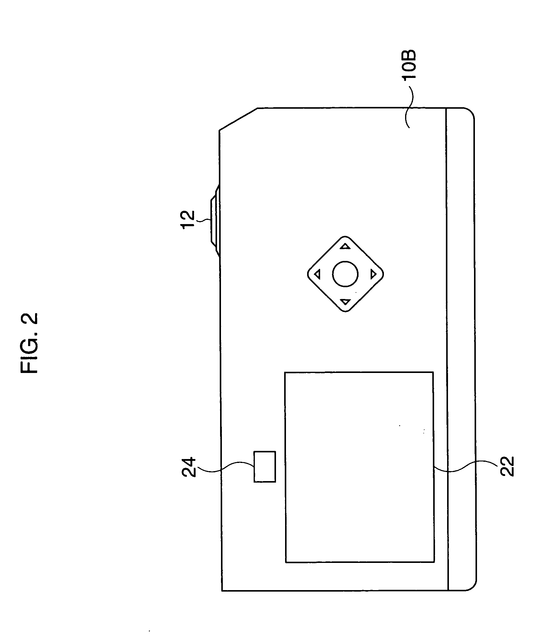
[0034] The back surface 10B is provided with a liquid crystal monitor (an indicating device) 22 where the object image is displayed, and a finder window 24 of an optical finder. The object image which is taken by the photographing optical system 14 is displayed on the monitor 22 while the re...

fourth embodiment

[0084] However, in the fourth embodiment, the predetermined radiation cycle is much shorter than the exposure cycle and the quantity of pre-imaging light during each of the exposure periods is almost the same. Therefore, the user does not notice the quantity difference between each exposure cycle and the pre-imaging light does not flicker either.

[0085] In the fourth embodiment, the pre-imaging light is radiated except for during the exposure period TB1 and is not used for lighting the object displayed on the monitor 22. However, the CPU 15 does not have to control the LCD 48 in order to synchronize the light-pulse series with exposure cycle as in the first embodiment.

[0086] Further, the user does not feel that the pre-imaging light is flickering, if the frequency of the light pulse is not less than 300 Hz.

[0087] In the fifth embodiment, the light pulse of the pre-imaging light is the same as that in the fourth embodiment. However, the light-pulse series during each of the exposure...


PUM


Abstract

A photographing apparatus for photographing an object comprises a lighting device. The light device has a light source and a light-control apparatus. The light source radiates pre-imaging light before the object is photographed, and radiates imaging light when the object is photographed. The light-control apparatus controls the light source so that the quantity of the pre-imaging light is smaller than that of the imaging light.

Description

BACKGROUND OF THE INVENTION [0001] 1. Field of the Invention [0002] The present invention relates to a lighting device for photographing apparatus, in particular a portable apparatus having photographing device for example a digital camera, a portable telephone, and so on. [0003] 2. Description of the Related Art [0004] Conventionally, it is suggested that besides xenon lamps, semiconductor lighting devices, for example a white LED (light emitting diode), can be used as lighting devices for a photographing apparatus. While semiconductor lighting devices have the advantage of higher luminous efficiency, the quantity of light they produce is small. [0005] A lighting device for photographing, having a white LED as the light source, is disclosed by Japanese Unexamined Patent Publication (KOKAI) NO.2003-101836 for example. In this reference, the photographing apparatus can photograph a moving image by forming many object image frames intermittently. And the lighting device radiates a str...

Claims


Application Information

Patent Timeline
Patent Type & Authority Applications(United States)
IPC IPC(8): G03B7/28G03B7/16G03B15/03G03B15/05H04N5/225H04N5/238H04N101/00H05B41/32
CPCH04N5/23241H04N5/2256H04N23/56H04N23/651
Inventor SEO, SHUZO
Owner ASAHI KOGAKU KOGYO KK
Why Eureka
Try Eureka