Composite material progressing cavity stators

a composite material and progressing cavity technology, applied in the direction of liquid fuel engines, machines/engines, rotary piston liquid engines, etc., can solve the problems of considerable time and expense savings in replacing damaged inserts in the field, and achieve the effects of improving reliability, cost saving, and prolonging service li

a composite material and progressing cavity technology, applied in the direction of liquid fuel engines, machines/engines, rotary piston liquid engines, etc., can solve the problems of considerable time and expense savings in replacing damaged inserts in the field, and achieve the effects of improving reliability, cost saving, and prolonging service li

US20050089429A1Inactive Publication Date: 2005-04-28DYNA DRILL TECH

Image

  • Composite material progressing cavity stators
  • Composite material progressing cavity stators
  • Composite material progressing cavity stators

Examples


Embodiment Construction

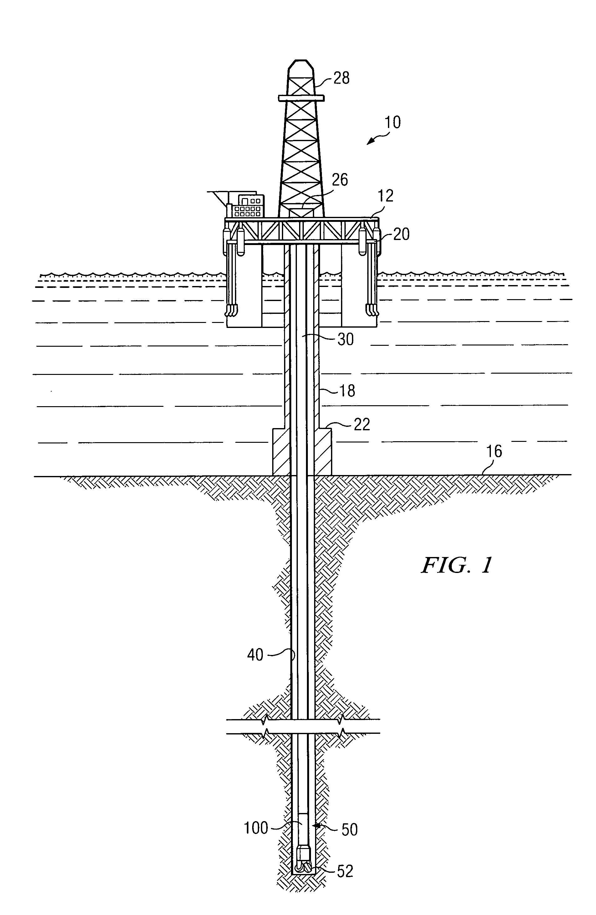
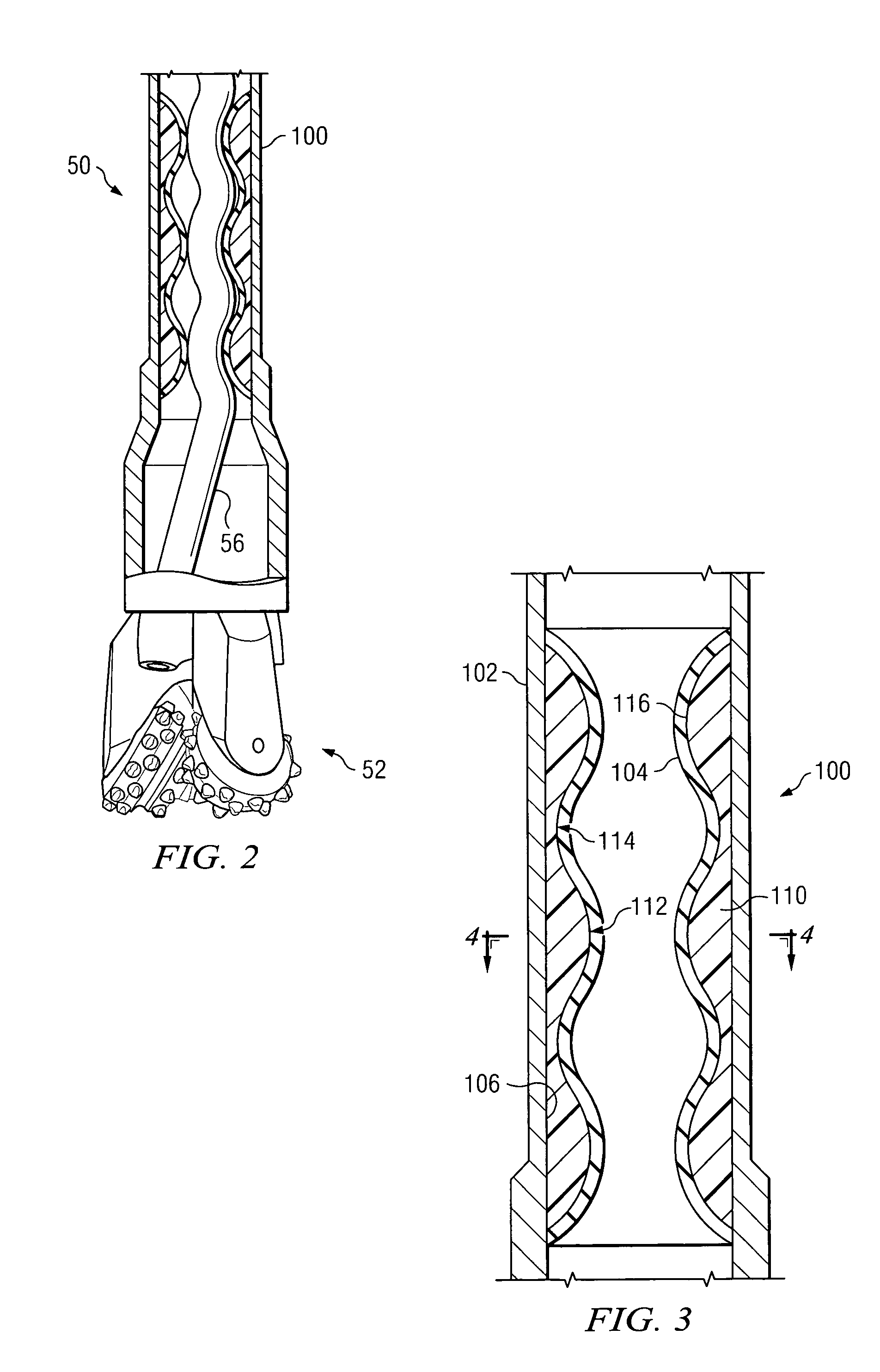
[0021]FIGS. 1 and 2 illustrate one exemplary embodiment of a progressing cavity stator 100 according to this invention in use in an offshore oil or gas drilling assembly, generally denoted 10 on FIG. 1. In FIG. 1, a semisubmersible drilling platform 12 is positioned over an oil or gas formation (not shown) disposed below the sea floor 16. A subsea conduit 18 extends from deck 20 of platform 12 to a wellhead installation 22. The platform may include a derrick 26 and a hoisting apparatus 28 for raising and lowering the drill string 30, which, as shown, extends into borehole 40 and includes a progressing cavity motor 50 coupled to a drill bit assembly 52. In FIG. 2, the progressing cavity motor 50 includes a rotor 56 operational within a progressing cavity stator 100. As described in more detail below, the stator 100 includes a fiber reinforced composite component.

[0022] It will be understood by those of ordinary skill in the art that the progressing cavity stator 100 of the present i...


PUM

PropertyMeasurementUnit
diameteraaaaaaaaaa
inner diameteraaaaaaaaaa
outer diameteraaaaaaaaaa

Abstract

A progressing cavity stator is provided. The progressing cavity stator includes a fiber reinforced composite component providing an internal helical cavity having at least one helical groove and an elastomeric liner disposed on an internal surface of the fiber reinforced composite component. In various exemplary embodiments, the fiber reinforced composite component includes a plurality of fibers disposed in a matrix material, the plurality of fibers being disposed such that distinct portions thereof follow correspondingly distinct directions. Exemplary embodiments of this invention may advantageously exhibit a prolonged service life in downhole applications as compared to conventional progressing cavity stators. A replaceable progressing cavity insert for a stator is also provided. Methods for fabricating progressing cavity stators and progressing cavity inserts are also provided.

Description

FIELD OF THE INVENTION [0001] The present invention relates generally to progressing cavity hydraulic drilling motors, typically for downhole use. This invention more specifically relates to fiber reinforced composite stators and methods for fabricating fiber reinforced composite stators. BACKGROUND OF THE INVENTION [0002] Progressing cavity hydraulic motors and / or pumps are well known in downhole drilling and artificial lift applications, such as for oil and / or gas exploration. Such progressing cavity motors make use of hydraulic power from drilling fluid to provide power, for example, to a drill bit assembly. The power section of a typical progressing cavity motor includes a helical rotor disposed within the cavity of a corresponding stator and converts the hydraulic power of high pressure drilling fluid to mechanical power (e.g., torque). Flow of the high pressure drilling fluid down through the rotor stator assembly rotates the rotor relative to the stator (which is usually conn...

Claims


Application Information

Patent Timeline
28 Apr 2005
Publication
US20050089429A1
IPC
F04C2/107; F04C13/00
CPC
F04C2/1075; F05C2253/04; F04C13/008
Inventors
DELPASSAND, MAJID S.; GALLAGHER, JAMES