Video transmitting device, receiving device, video transmitting system, video transmitting method, video transmitting program, and storage medium storing video transmitting program

a video transmitting and video data technology, applied in the field of video transmitting devices, video transmitting systems, video transmitting programs, and video transmitting programs, can solve the problems of complex user operation of remote control, inability to choose a video data transmitting scheme suitable for the receiving device, and inability to reproduce video data in the above-described manner

Inactive Publication Date: 2005-04-28
SHARP KK
View PDF5 Cites 18 Cited by
  • Summary
  • Abstract
  • Description
  • Claims
  • Application Information

AI Technical Summary

Benefits of technology

[0023] The present invention was made in light of the foregoing problems. An object of the present invention is therefore to provide a video transmitting device, a receiving device, a video transmitting system, a video transmitting method, a video transmitting program, and a storage medium storing the video transmitting program, each of which make it possible to view video data in a PC by using a device on the side of the receiving device by minimum instructions, and to choose a video data transmitting scheme in accordance with a function of the receiving device.

Problems solved by technology

However, if a user chooses to use a TV monitor to view a video stored in a PC, there are the following problems.
On the other hand, if the receiver-side device is a TV set, and a monitor of the TV set is used for reproducing a video, the video data cannot be reproduced in the above-described manner, unlike the case in which the file is transmitted and received between PCs.
This is because the TV set, which is designed to reproduce video data inputted as an analog A / V signal, does not have an external input device for handling a video file stored in a PC.
This causes a problem that operating the remote control is complex for a user.
Another problem of the conventional system including a PC that stores video data and a receiving device that receives the video data is that the PC cannot choose a video data transmitting scheme suitable for the receiving device by judging a function of the receiving device.

Method used


Image

  • Video transmitting device, receiving device, video transmitting system, video transmitting method, video transmitting program, and storage medium storing video transmitting program
  • Video transmitting device, receiving device, video transmitting system, video transmitting method, video transmitting program, and storage medium storing video transmitting program
  • Video transmitting device, receiving device, video transmitting system, video transmitting method, video transmitting program, and storage medium storing video transmitting program

Examples


first embodiment

[0050] (First Embodiment)

[0051] First, with reference to FIGS. 1 to 6, a first embodiment of the present invention is described below.

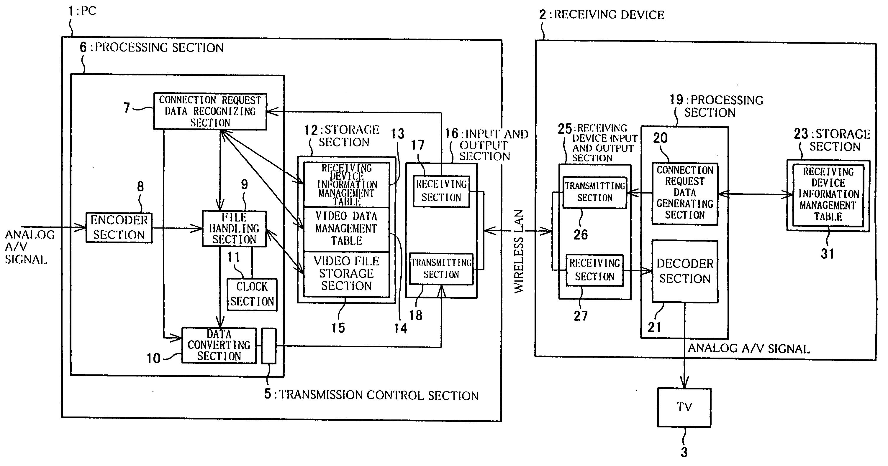
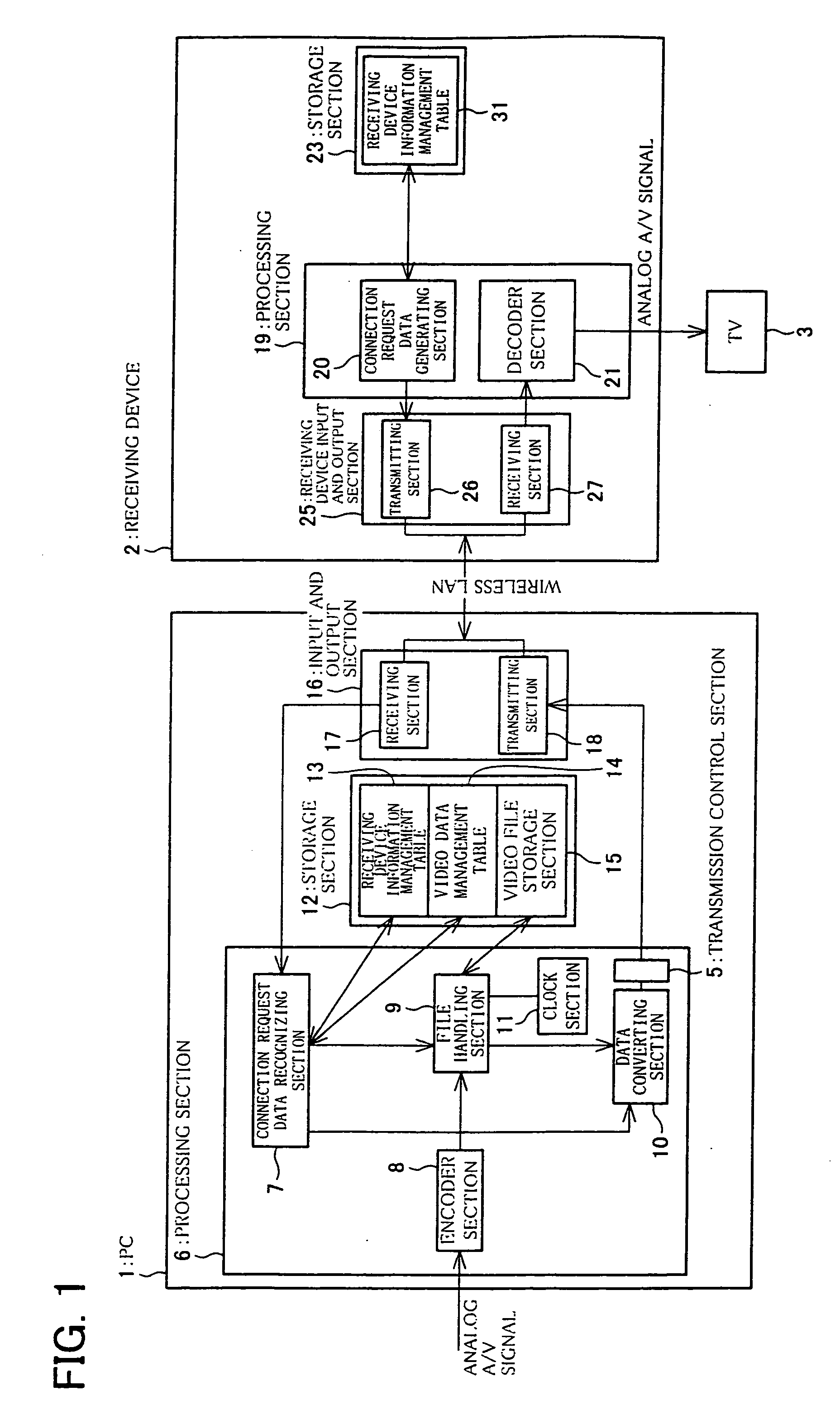
[0052]FIG. 1 is a diagram illustrating an example of a video transmitting system for transmitting video data between a PC 1 and a receiving device 2, which are connected to each other by wireless. The system of the present embodiment transmits video data stored in the PC 1 to the receiving device over a wireless LAN. The video can be displayed on a monitor of a TV set 3, which is connected to the receiving device 2.

[0053] In the present embodiment, the PC 1 and the receiving device 2 are connected to each other through a wireless LAN. However, any form of communication may be performed between the PC 1 and the receiving device 2, as long as wireless communication is possible. Alternatively, the PC 1 and the receiving device 2 may be connected by wire, instead of being connected by wireless.

[0054] The system includes the PC (video transmitting devic...

second embodiment

[0155] (Second Embodiment)

[0156] With reference to FIGS. 7 to 9, the following describes “Second Embodiment”, as another embodiment of the system of the present invention. FIG. 7 is a block diagram illustrating another embodiment of the system of the present invention.

[0157] In a system (second system) of the Second Embodiment, video data stored in the PC 1 is transmitted to the receiving device 2 over a wireless LAN, and the video is viewed by using a monitor of the TV set 3, which is connected to the receiving device 2.

[0158] As in the system of the First Embodiment, the PC 1 and the receiving device 2 may not be connected to each other over the wireless LAN. Any form of communication may be performed between the PC 1 and the receiving device 2, as long as wireless communication is possible. Alternatively, the PC 1 and the receiving device 2 may be connected by wire, instead of being connected by wireless.

[0159] The system of the Second Embodiment is different from the system o...


PUM


Abstract

A PC includes a processing section and a storage section. The processing section controls operation of the PC, based on connection request data for requesting a connection. The connection request data is transmitted from a receiving device. The storage section stores video to be transmitted to the receiving device. When a connection request data recognizing section of the processing section recognizes the connection request data, a connection is established between the PC and the receiving device that transmitted the connection request data, and a transmission control section transmits a video data file read by a file handling section. In the PC, the processing section includes the connection request data recognizing section and the file handling section. Therefore, even if no instruction is made from the side of the receiving device to the PC by using a remote control, it is possible to transmit video data from the PC to the receiving device, and to reproduce the video data. In addition, the PC can transmit the video data by a transmitting scheme that is in accordance with a function of the receiving device.

Description

BACKGROUND OF THE INVENTION [0001] (Watching Video by Using TV Set) [0002] In order to view videos, it has been a general practice to use a TV set. In addition to viewing videos transmitted in real time, users can now view desired video contents anytime, by using a videotape recorder, a DVD recorder, or the like device (video recording and reproducing device). [0003] Recently, a video wireless transmitting system has been put into practical use. In the video wireless transmitting system, a TV set and a video recording and reproducing device are connected by wireless. A video signal recorded by the video recording and reproducing device is digitalized, and transmitted to the TV set, which is installed at a remote location. One example of such a system is a wireless transmitting system shown in FIG. 10. FIG. 10 is a block diagram illustrating a wireless communication system including a videotape recorder / DVD recorder (video recording and reproducing device) 105 and a TV set 103. [0004...

Claims


Application Information

Patent Timeline
Patent Type & Authority Applications(United States)
IPC IPC(8): H04N5/765H04J3/18H04N5/38H04N5/76H04N7/173H04N21/436H04N21/4402H04N21/442
CPCH04N21/4108H04N21/4135H04N21/4143H04N21/4147H04N21/43637H04N21/42661H04N21/432H04N21/4334H04N21/4363H04N21/42204
Inventor HOGYOKU, ITARU
Owner SHARP KK
Why Eureka
Try Eureka