Method and apparatus for exhaust gas recirculation cooling using a vortex tube to cool recirculated exhaust gases

Inactive Publication Date: 2005-05-05
CATERPILLAR INC
View PDF19 Cites 9 Cited by
  • Summary
  • Abstract
  • Description
  • Claims
  • Application Information

AI Technical Summary

Problems solved by technology

The exhaust gas which is reintroduced to the engine cylinder reduces the concentration of oxygen therein, which in turn lowers the maximum combustion temperature within the cylinder and slows the chemical reaction of the combustion process, decreasing the formation of nitrous oxides (NOx).
However, such devices require an increase in the overall heat rejection capability of the engine.

Method used


Image

  • Method and apparatus for exhaust gas recirculation cooling using a vortex tube to cool recirculated exhaust gases
  • Method and apparatus for exhaust gas recirculation cooling using a vortex tube to cool recirculated exhaust gases
  • Method and apparatus for exhaust gas recirculation cooling using a vortex tube to cool recirculated exhaust gases

Examples


Embodiment Construction

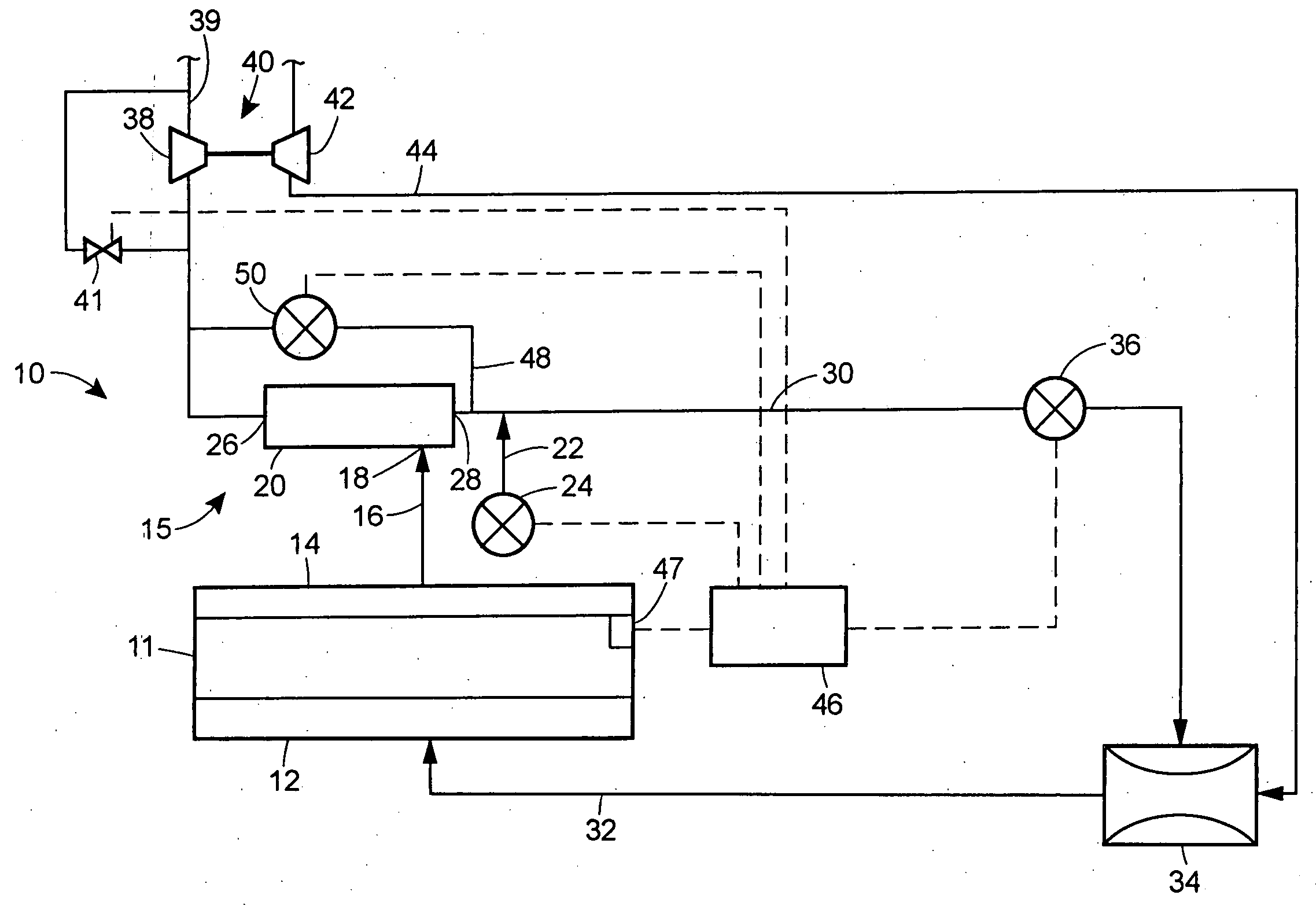
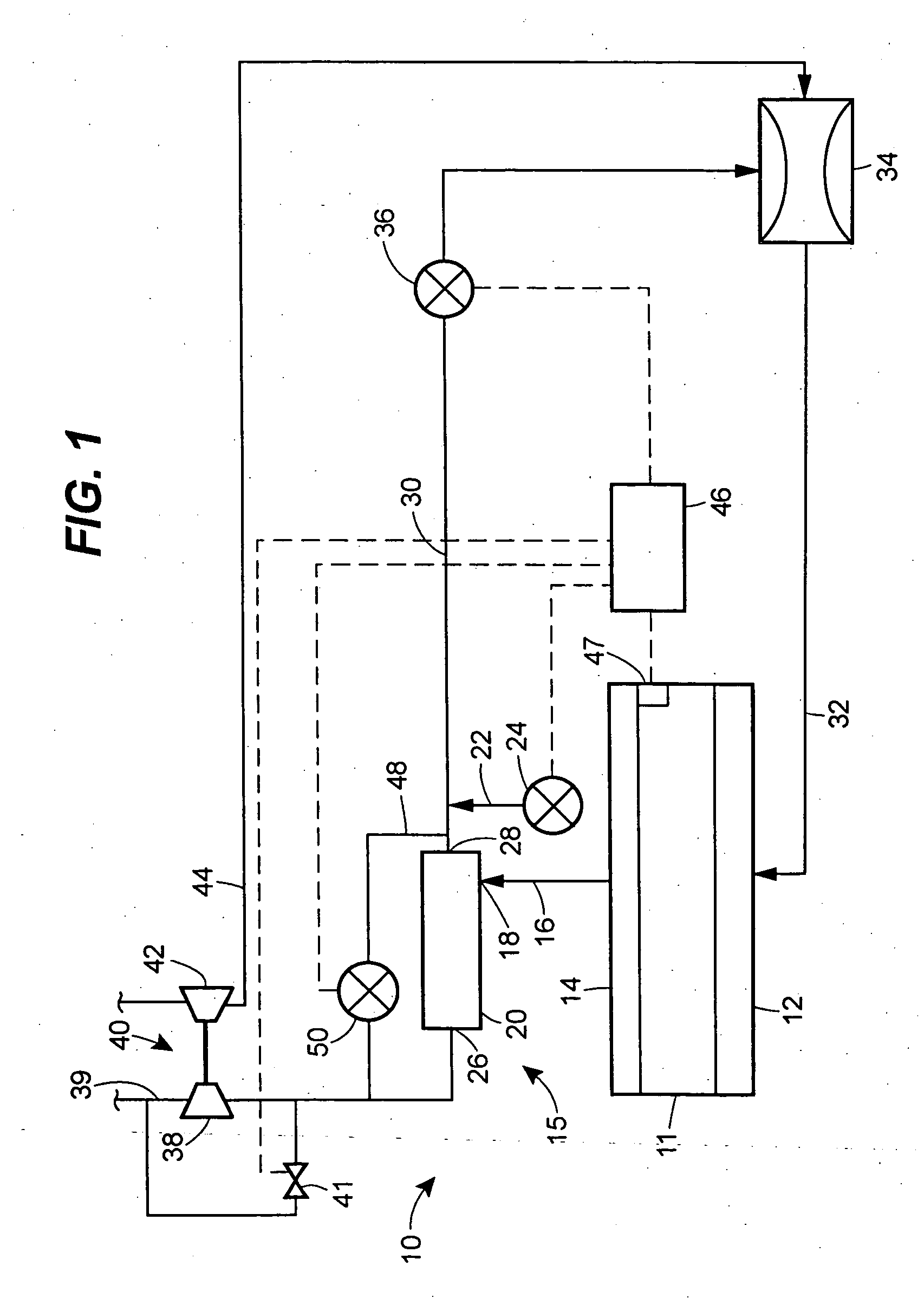
[0012] With reference to FIG. 1, an engine, shown schematically, and generally indicated at 10, may include a combustion chamber 11, an intake manifold 12 and an exhaust manifold 14. The engine 10 may further include means 15 for recirculating exhaust gases, which may include a primary exhaust gas recirculation conduit 16 in fluid communication with the exhaust manifold 14. The primary exhaust gas recirculation conduit 16 may also be in fluid communication with an inlet 18 of a vortex tube 20. The primary exhaust gas recirculation conduit 16 may also optionally be in fluid communication with a bypass conduit 22 having a bypass valve 24 therein. The vortex tube 20 includes a hot gas outlet 26 and a cold outlet 28 and may be capable of diverting relatively hot exhaust gases to the hot gas outlet 26, and relatively cold gas exhaust gases to the cold gas outlet 28.

[0013] The cold gas outlet 28 of the vortex tube 20 may be placed in fluid communication with a cold exhaust gas recirculat...


PUM


Abstract

An engine includes an exhaust conduit, an intake conduit, and a vortex tube disposed between the exhaust conduit and the intake conduit. The vortex tube has an inlet in fluid communication with the exhaust conduit, a cold gas outlet in fluid communication with the intake conduit, and a hot gas outlet.

Description

TECHNICAL FIELD [0001] The present invention relates generally to engines and, more particularly, to cooling recirculated exhaust gases in engines. BACKGROUND [0002] In order to minimize pollutants such as NOX, internal combustion engines may include an exhaust gas recirculation (EGR) system that includes an EGR valve. EGR systems primarily recirculate exhaust gas by-products into the intake air supply of the internal combustion engine. The EGR valve can be used to redirect a portion of exhaust gases to an intake conduit, such as an intake manifold, so that the redirected exhaust gases will be recycled. [0003] The exhaust gas which is reintroduced to the engine cylinder reduces the concentration of oxygen therein, which in turn lowers the maximum combustion temperature within the cylinder and slows the chemical reaction of the combustion process, decreasing the formation of nitrous oxides (NOx). Furthermore, the exhaust gases typically contain unburned hydrocarbons that are burned o...

Claims


Application Information

Patent Timeline
IPC IPC(8): F02B33/44F02B37/00F02B37/18F02M25/06F02M25/07
CPCF02B37/00F02B37/18F02M25/0707F02M25/0709F02M25/0713Y02T10/144F02M25/0728F02M25/0751F02M25/0754Y02T10/121F02M25/0727F02M26/05F02M26/06F02M26/10F02M26/23F02M26/25F02M26/44F02M26/47Y02T10/12
Inventor HOLTMAN, RICHARD H.CAVANAGH, MARK S.
Owner CATERPILLAR INC
Why Eureka
Try Eureka