Method and system for controlling a flowrate of a recirculated exhaust gas

Active Publication Date: 2009-05-19
GENERAL ELECTRIC CO
View PDF8 Cites 140 Cited by
  • Summary
  • Abstract
  • Description
  • Claims
  • Application Information

AI Technical Summary

Benefits of technology

[0008]In accordance with an embodiment of the present invention, a method of controlling an exhaust stream, wherein the exhaust stream is generated by a turbomachine; the method comprising: providing at least one exhaust gas recirculation (EGR) system comprising: at least one EGR flow conditioning device, a constituent reduction system, at least one flow control device; wherein the at least one EGR flow conditioning device increases the flowrate of the exhaust stream and comprises a source of air; wherein the source of air comprises a fan, wherein the EGR system reduces constituents within the exhaust stream from a first concentration to a second concentration and recirculates the exhaust stream to an inlet section of the turbomachine; receiving a target EGR fraction comprising the portion of the exhaust stream within an inlet fluid, wherein the inlet fluid enters the inlet section of the turbomachine; determining a target level of at least one constituent from the target EGR fraction; determining a current level of the at least one constituent; determining whether the current level of the at least one constituent is within a constituent range; and adjusting a recirculation rate of the exhaust stream if the at least one constituent is outside of the constituent range.
[0009]In accordance with an alternate embodiment of the present invention, a method of controlling an exhaust stream, wherein the exhaust stream is generated by a turbomachine; the method comprising: providing at l

Problems solved by technology

Left untreated, these constituents will accelerate corrosion and fou

Method used


Image

  • Method and system for controlling a flowrate of a recirculated exhaust gas
  • Method and system for controlling a flowrate of a recirculated exhaust gas
  • Method and system for controlling a flowrate of a recirculated exhaust gas

Examples


Embodiment Construction

[0014]The following detailed description of preferred embodiments refers to the accompanying drawings, which illustrate specific embodiments of the invention. Other embodiments having different structures and operations do not depart from the scope of the present invention.

[0015]Certain terminology is used herein for the convenience of the reader only and is not to be taken as a limitation on the scope of the invention. For example, words such as “upper,”“lower,”“left,”“right,”“front”, “rear”“top”, “bottom”, “horizontal,”“vertical,”“upstream,”“downstream,”“fore”, “aft”, and the like; merely describe the configuration shown in the Figures. Indeed, the element or elements of an embodiment of the present invention may be oriented in any direction and the terminology, therefore, should be understood as encompassing such variations unless specified otherwise.

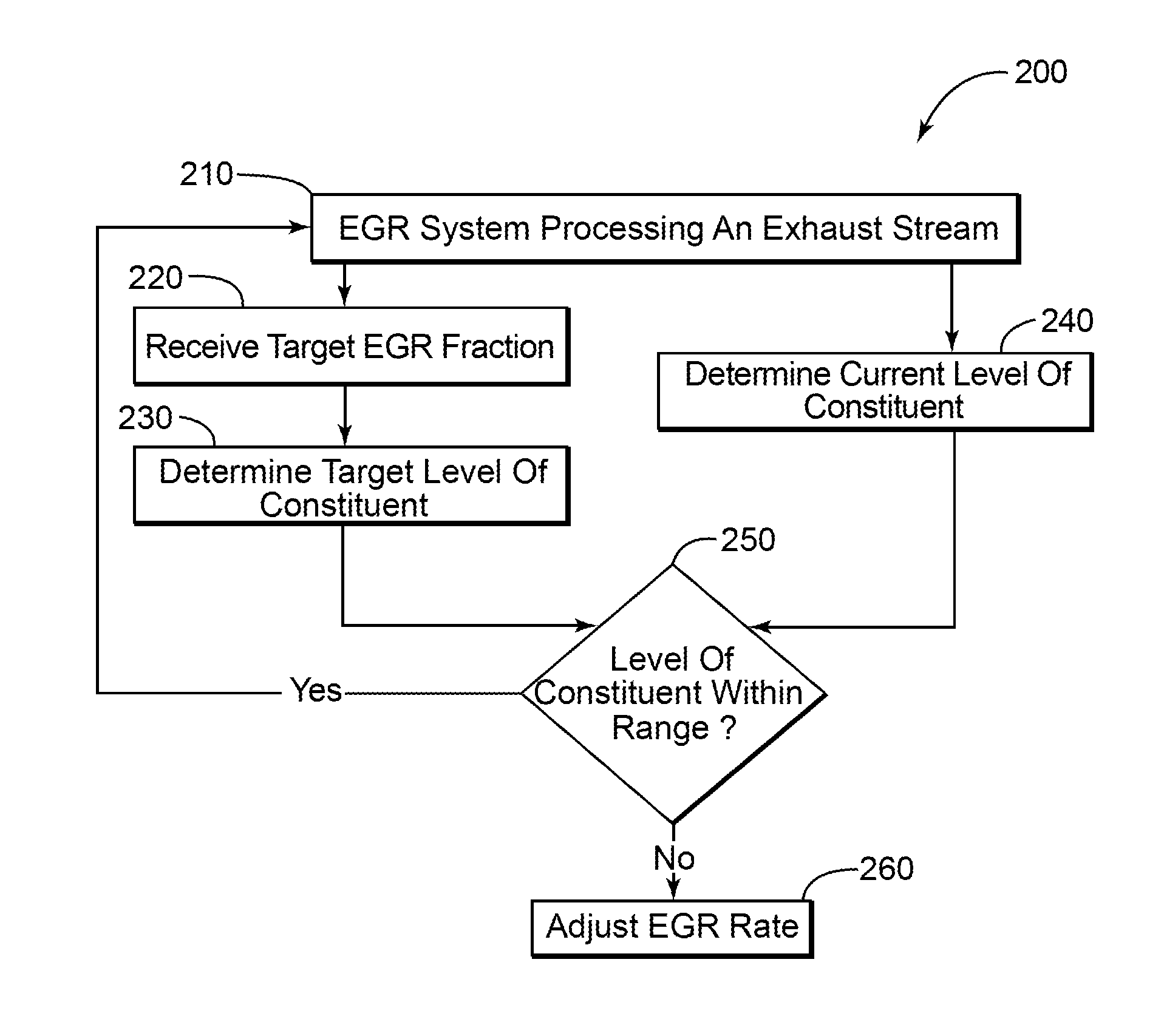
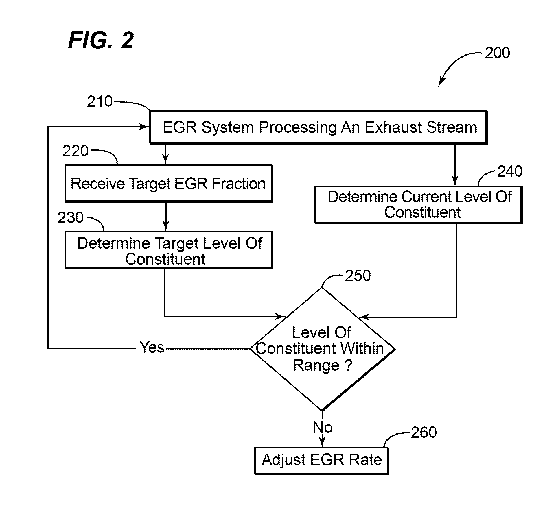
[0016]The present invention has the technical effect of controlling the composition of an inlet fluid exiting an EGR system and ent...


PUM


Abstract

A method and system for controlling an exhaust gas recirculation (EGR) system is provided. The EGR system recirculates a portion of an exhaust through an inlet portion of the turbomachine. The EGR system reduces the level of harmful constituents within the exhaust before the recirculation occurs.

Description

BACKGROUND OF THE INVENTION[0001]This application is related to commonly-assigned U.S. patent application Ser. No. 11 / 928,038, filed Oct. 30, 2007 and U.S. patent application Ser. No. 11 / 953,524, filed Dec. 10, 2007.[0002]The present invention relates to an exhaust gas recirculation system, and more particularly to a method and system for controlling the quantity of exhaust reentering a turbomachine after processing by a recirculation system.[0003]There is a growing concern over the long-term effects of Nitrogen Oxides (hereinafter NOx) and Carbon Dioxide (hereinafter “CO2”) and Sulfur Oxides (SOx) emissions on the environment. The allowable levels of emissions that may be emitted by a turbomachine, such as a gas turbine, are heavily regulated. Operators of turbomachines desire methods of reducing the levels of NOx, CO2, and SOx emitted.[0004]Significant amounts of condensable vapors exist in the exhaust gas stream. These vapors usually contain a variety of constituents such as wate...

Claims


Application Information

Patent Timeline
IPC IPC(8): B60T7/12F02M25/07
CPCF02C3/34Y02E20/16
Inventor HIBSHMAN, II, JOELL R.DRAPER, SAM D.
Owner GENERAL ELECTRIC CO
Why Eureka
Try Eureka