Approach for Delivering a Liquid Reductant into an Exhaust Flow of a Fuel Burning Engine

a technology of liquid reductant and fuel burning engine, which is applied in the direction of machines/engines, mechanical equipment, transportation and packaging, etc., can solve the problems of catalyst degradation, insufficient evaporation rate, and additional challenges of the use of scr systems in non-stationary or vehicle related applications, so as to reduce the cost of injectors and increase the distance of travel

Active Publication Date: 2009-01-22
FORD GLOBAL TECH LLC
View PDF13 Cites 142 Cited by
  • Summary
  • Abstract
  • Description
  • Claims
  • Application Information

AI Technical Summary

Benefits of technology

[0003]As set forth by the present disclosure, an exhaust system for an internal combustion engine for a vehicle is provided. The exhaust system comprises an exhaust passage for transporting exhaust gases from the engine; an injector coupled to a wall of the exhaust passage, said injector including an injection axis that is angled relative to a longitudinal axis of a mixing region of the exhaust passage; and a first mixing device arranged within the exhaust passage downstream of the injector within the mixing region, said first mixing device including a plurality of flaps, wherein said plurality of flaps are inclined relative to the longitudinal axis; a second mixing device arranged within the exhaust passage downstream of the first mixing device; wherein the injection axis of the injector intersects the first mixing device. As one example, the second mixing device may be configured as a helical mixer for increasing the distance of travel of the liquid reductant and exhaust gases flowing through the exhaust passage.
[0004]In this way, by utilizing the synergistic effects of the first mixing device for redirecting and increasing break-up of the liquid reductant and the second mixing device arranged downstream of the first mixing device, the reductant may be sufficiently mixed with exhaust gases produced by the engine before reaching a catalyst even where a relatively course spray is used by the injector, thereby reducing the amount of unmixed reductant deposited on the catalyst or walls of the exhaust passage and enabling a reduction in injector cost.

Problems solved by technology

The use of SCR systems in non-stationary or vehicle related applications can pose additional challenges due to geometric constraints.
Some of these issues may be caused by an insufficient rate of evaporation and mixing of the injected liquid reductant with the exhaust gases as compared to the effective length of the mixing region.
For example, where the liquid reductant is not sufficiently evaporated and mixed with the exhaust gases before reaching the catalyst, drops of liquid may be deposited onto the catalyst, which may leave residue upon evaporation and may eventually lead to degradation of the catalyst.

Method used


Image

  • Approach for Delivering a Liquid Reductant into an Exhaust Flow of a Fuel Burning Engine
  • Approach for Delivering a Liquid Reductant into an Exhaust Flow of a Fuel Burning Engine
  • Approach for Delivering a Liquid Reductant into an Exhaust Flow of a Fuel Burning Engine

Examples


Embodiment Construction

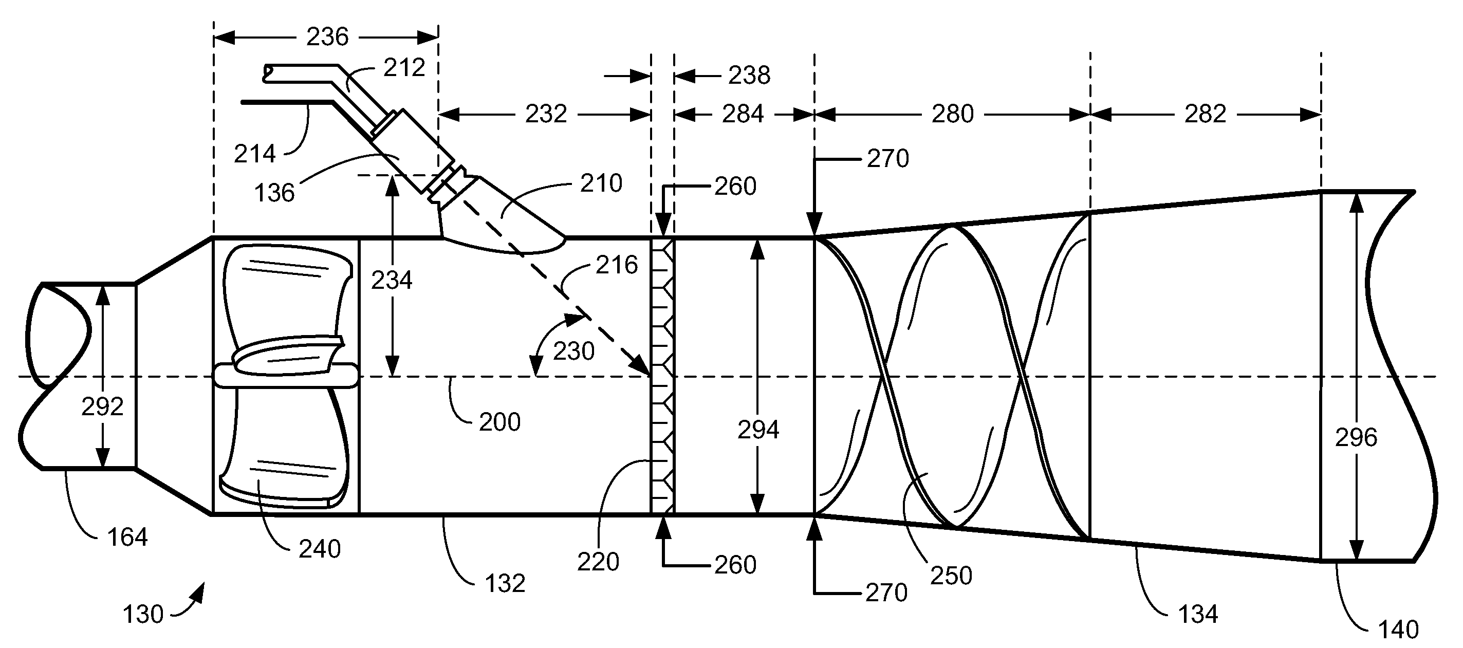
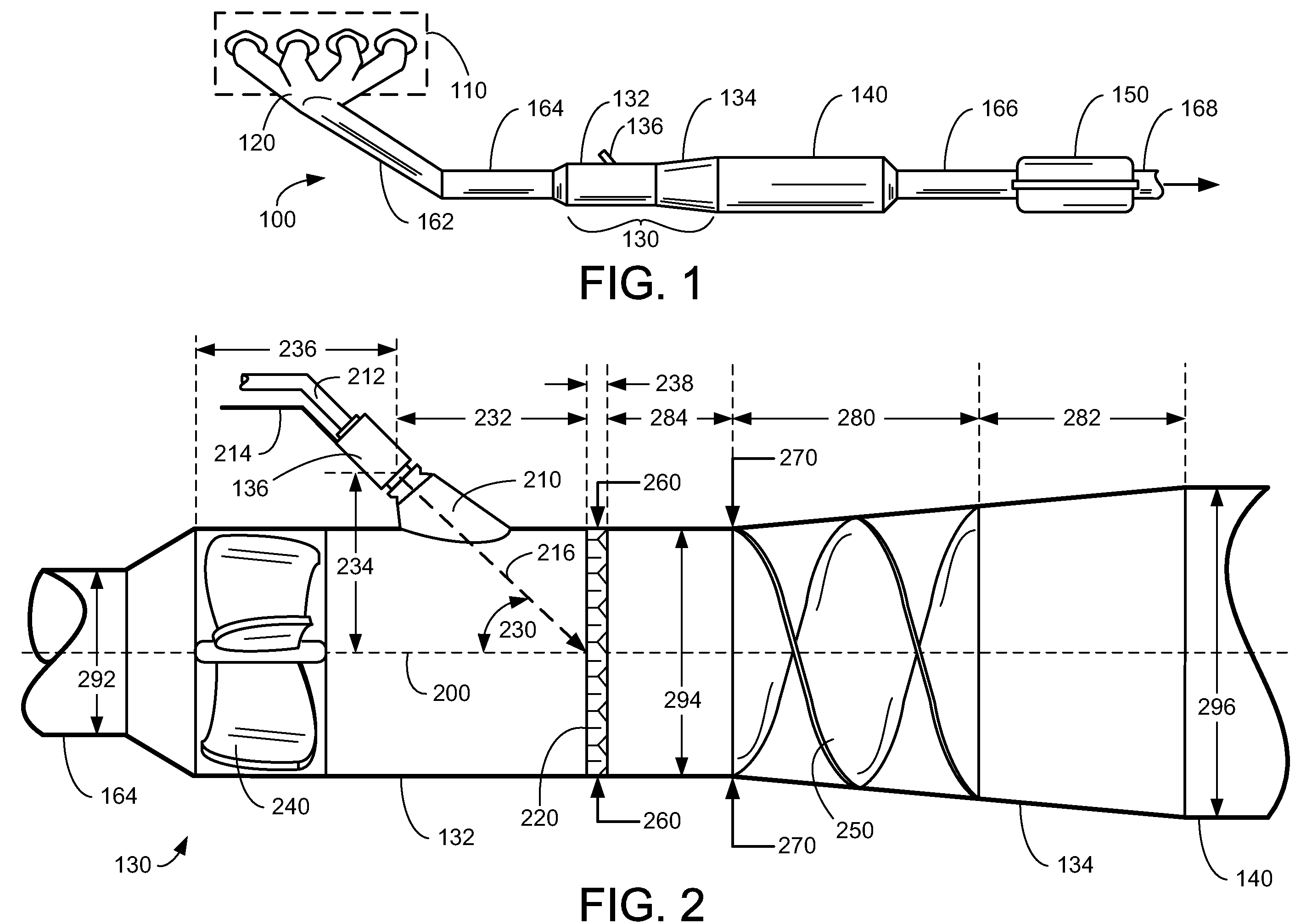
[0012]FIG. 1 illustrates an exhaust system 100 for transporting exhaust gases produced by internal combustion engine 110. As one non-limiting example, engine 110 includes a diesel engine that produces a mechanical output by combusting a mixture of air and diesel fuel. Alternatively, engine 110 may include other types of engines such as gasoline burning engines, among others. In some embodiments, engine 110 may be configured in a propulsion system for a vehicle. However, in other embodiments, engine 110 may be operated in a stationary application such as an electric generator, for example. While exhaust system 100 may be applicable to stationary applications, it should be appreciated that exhaust system 100 as described herein, is particularly adapted for vehicle applications, particularly where geometric limitations limit the mixing region of the exhaust gases and reductant.

[0013]Exhaust system 100 may include one or more of the following: an exhaust manifold 120 for receiving exhau...


PUM

PropertyMeasurementUnit
angleaaaaaaaaaa
angleaaaaaaaaaa
angleaaaaaaaaaa

Abstract

An exhaust system for an internal combustion engine for a vehicle is provided. The system comprises an exhaust passage for transporting exhaust gases from the engine; an injector coupled to a wall of the exhaust passage, said injector including an injection axis that is angled relative to a longitudinal axis of a mixing region of the exhaust passage; and a first mixing device arranged within the exhaust passage downstream of the injector within the mixing region, said first mixing device including a plurality of flaps, wherein said plurality of flaps are inclined relative to the longitudinal axis; a second mixing device arranged within the exhaust passage downstream of the first mixing device; wherein the injection axis of the injector intersects the first mixing device.

Description

BACKGROUND AND SUMMARY [0001]Exhaust after-treatment systems may be used to treat exhaust gases produced by a fuel burning engine. As one example, diesel engines may utilize an exhaust system that includes a selective catalytic reduction (SCR) system for reducing the amount of NOx that is ultimately discharged to the surrounding environment during operation of the engine. An SCR system may utilize the injection of a liquid reductant such as ammonia or urea into the exhaust gases where they may be mixed and absorbed onto a catalyst. The liquid reductant as it is evaporated and / or mixed with the exhaust gases can react with the nitrogen oxide (NOx) component of the exhaust gases to form water vapor and nitrogen gas.[0002]The use of SCR systems in non-stationary or vehicle related applications can pose additional challenges due to geometric constraints. Some of these issues may be caused by an insufficient rate of evaporation and mixing of the injected liquid reductant with the exhaust...

Claims


Application Information

Patent Timeline
Patent Type & Authority Applications(United States)
IPC IPC(8): F01N3/10
CPCB01F3/04049B01F5/0268B01F5/0473B01F5/0614B01F5/0618Y02T10/24F01N3/2892F01N2240/20F01N2610/02F01N2610/1453F01N3/2066Y02A50/20Y02T10/12B01F23/2132B01F25/25B01F25/3141B01F25/4314B01F25/4316
Inventor LEVIN, MICHAELBALESTRINO, SANDROKABAT, DANIEL MICHAELSHAIKH, FURQAN ZAFARZIMMERMAN, BRET ALANKELLER, JEREMYCOOPER, SCOTT DONALDKANTEBET, KRIS
Owner FORD GLOBAL TECH LLC
Why Eureka
Try Eureka