Integral-type heat exchanger

a heat exchanger and integrated technology, applied in indirect heat exchangers, stationary tubular conduit assemblies, lighting and heating apparatus, etc., to achieve the effect of simple structure and reduction of the thickness of the heat radiation section (or core)

Inactive Publication Date: 2005-05-05
CALSONIC KANSEI CORP
View PDF20 Cites 6 Cited by
  • Summary
  • Abstract
  • Description
  • Claims
  • Application Information

AI Technical Summary

Benefits of technology

[0013] This invention has been conceived to solve the aforementioned problem, and the object of the present invention is to provide an integral-type heat exchanger which enables a reduction in the thickness of a heat radiation section (or core) in a simple structure.
[0016] According to the present invention, the tubes of the first and second heat exchangers are held in parallel with each other, and the tanks of the second heat exchanger are brought into contact with the plane sections of the first heat exchanger. As a result, it is possible to minimize the distance between the tubes.
[0017] Further, the length of the second heat exchanger can be minimized.
[0019] In the heat exchange tank according to the present invention, the lock members of the end plates act as whirl-stops of the end plates, and hence the end plates can be reliably fitted into the first and second heat exchange tanks.
[0021] Further, heat propagating through the corrugated fin from the first or second heat exchanger having a high operating temperature to the second or first heat exchanger having a lower operating temperature is effectively exchanged with air by the parallel louvers. As a result, a thermal influence is prevented from acting on the second or first heat exchanger having a low operating temperature.
[0022] The wind passing through both heat exchangers can flow in the direction of ventilation without increasing resistance of the parallel louvers.

Problems solved by technology

However, such a modification requires a difficult boring operation, and hence this idea is not suitable in view of practicality.

Method used


Image

  • Integral-type heat exchanger
  • Integral-type heat exchanger
  • Integral-type heat exchanger

Examples


1st embodiment

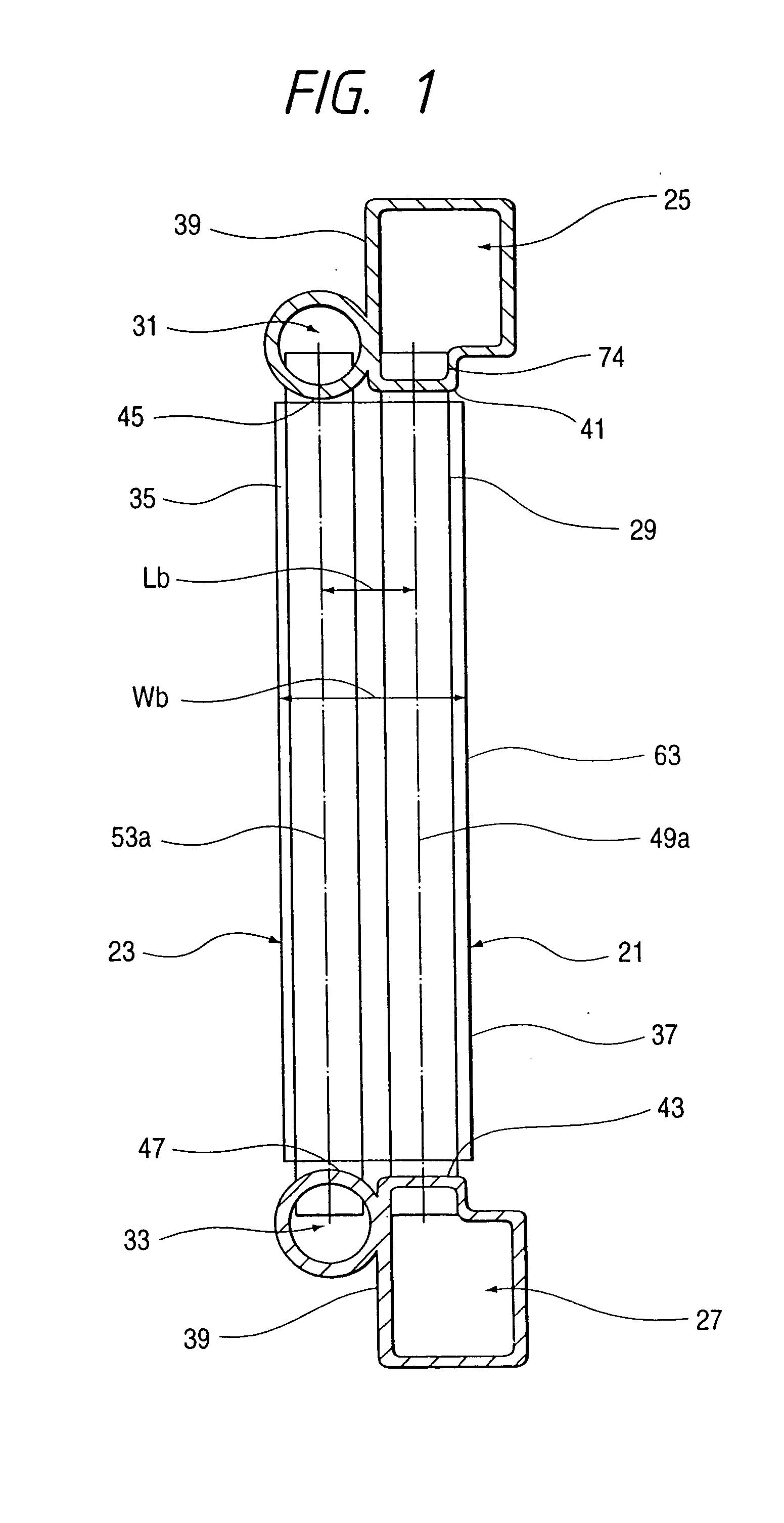
[0077] FIGS. 1 to 4 illustrate a first embodiment of an integral-type heat exchanger according to the present invention. In the drawings, reference numeral 21 designates a first heat exchanger constituting a radiator, and reference numeral 23 designates a second heat exchanger constituting a condenser. Incidentally, the inlet and outlet pipes, filler neck, or other members of the first and second heat exchangers are omitted in the drawings.

[0078] Tanks 25, 27 of the first heat exchanger 21 and the tanks 31, 33 of the second heat exchanger 23 are integrally molded from aluminum (e.g., A3003) by extrusion.

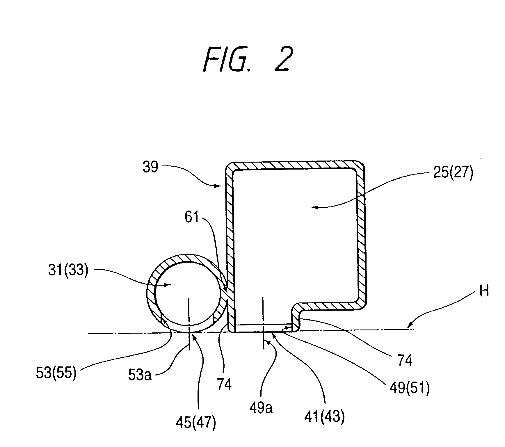
[0079] The tanks 25, 27 of the first heat exchanger 21 have rectangular cross sections, and the tanks 31, 33 of the second heat exchanger 23 have circular cross sections. The tanks 31, 33 of the second heat exchanger 23 are in contact with and are formed integrally with lower part of plane sections 39 formed in the side walls of the tanks 25, 27 of the first heat exchanger 21 throu...

2nd embodiment

[0099] The details of a second embodiment of the present invention will be described hereinbelow with reference to FIGS. 7 to 10. In FIG. 7, the common fin 37 to the first and second heat exchangers is used. However, is may be possible to adopt separated fins of each first and second heat exchangers.

[0100]FIG. 7 illustrates an integral-type heat exchanger which employs integral-types heat exchanger tanks according to this embodiment.

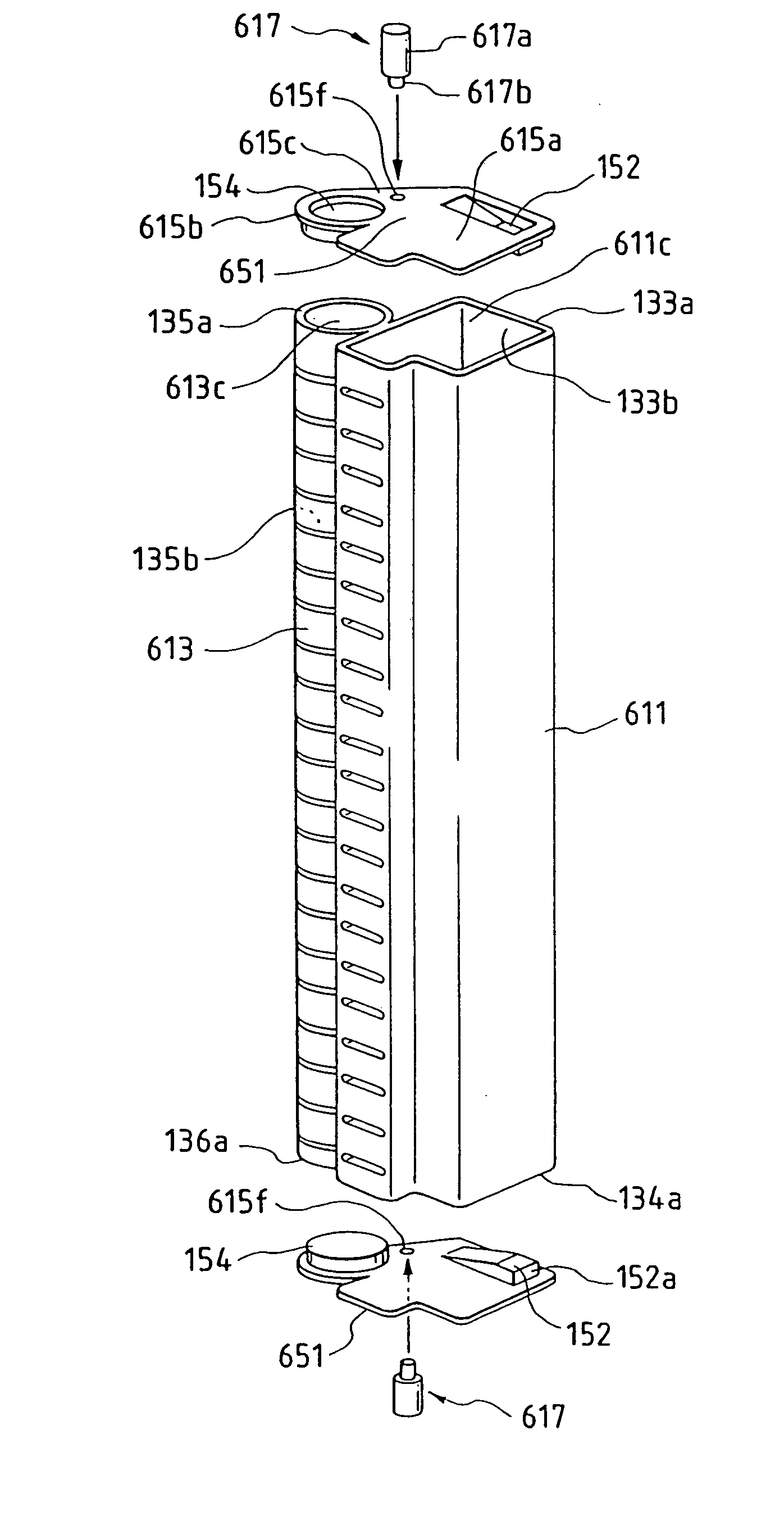
[0101] As illustrated in FIGS. 7, 9 and 10, end plates 151 made of brazing-material-clad aluminum (e.g., A4343-3003) are attached to open ends 133a, 134a, 135a, and 136a of the first and second heat exchanger tanks 25, 27, 31, and 33. The brazing material is positioned on the surface side facing the heat exchanger tanks. FIG. 8 shows a perspective view of integral-type heat exchanger tanks according to this embodiment.

[0102] Each end plate 151 is made from a single plate material which closes the first heat exchanger tanks 25, 27 and the second heat e...

3rd embodiment

[0112] In a third embodiment of the present invention, as illustrated in FIGS. 13 to 16, two attachment slots 251, 252 are formed in the second heat exchanger tanks 31, 33 so as to extend up to the joint 61. Partitions 252 which have a substantial ohm-shaped geometry and comprise brazing-material-clad aluminum (e.g., A4343-3003-4343; the brazing material being positioned on the both surface of the partition 252) are fitted into the attachment slots 251.

[0113] The partition 252 comprises a closing plate 253 which has the same shape as that of the attachment slot 251, and a lock piece 254 to be locked into the joint 61 between the first and second heat exchanger tanks 25, 27, 31, and 33.

[0114] In the integral-type heat exchanger having the foregoing structure according to the embodiment, the partitions 252 are fitted into the attachment slots 251 formed so as to extend up to the joint 61, with the lock piece 254 being inserted first. When a front end 254a of the lock piece 254 has c...


PUM


Abstract

Tanks of a first heat exchanger have plane sections perpendicular to bottoms having a plurality of tube insertion holes formed therein. Tanks of a second heat exchanger with circular cross sections have bottoms having a plurality of tube insertion holes formed therein. The axes of the tube insertion holes of the first and second heat exchangers are held in parallel with each other. The second heat exchanger is in contact with the plane sections of the first heat exchanger tank.

Description

BACKGROUND OF THE INVENTION [0001] 1. Field of the Invention [0002] The present invention relates to an integral-type heat exchanger comprising two-types of heat exchangers which are connected together or disposed adjacent to each other prior to mount on an automobile. [0003] 2. Description of the Related Art [0004] So-called integral heat exchangers have been recently developed, wherein a condenser for cooling purposes is connected to the front face of a radiator. An example of the integral heat exchangers is disclosed in Japanese Patent Publication No. Hei. 1-224163. [0005]FIG. 38 illustrates an integral-type heat exchanger as disclosed in Japanese Patent Publication No. Hei. 1-247990. This heat exchanger comprises a first heat exchanger 1 to be used as a radiator and a second heat exchanger 3 to be used as a cooling condenser, both of which are positioned in parallel with each other. [0006] The first heat exchanger 1 comprises an aluminum upper tank 5 which is opposite to and spa...

Claims


Application Information

Patent Timeline
Patent Type & Authority Applications(United States)
IPC IPC(8): F28D1/04F28F1/12F28F9/00F28F9/02F28F9/04F28F9/18
CPCF28D1/0435F28F2009/004F28D2021/0084F28D2021/0089F28D2021/0094F28F1/128F28F9/002F28F9/02F28F9/0202F28F9/0214F28F9/0246F28F9/0251F28F9/0256F28F9/18F28F2220/00F28F2275/143F28F2215/02F28F2009/0287F28D1/05375F28F21/084F28F2255/16
Inventor MAKINO, KENJIKOIZUMI, HIROYASUTSUCHIYA, MINORUMATSUGI, KUNIOCHIKUMA, HIROSHIISHIHARA, STAOSHITAJIMA, MAKOTOTSUDA, YOSHIKIYAMAMOTO, TOSHIAKIKOBAYASHI, HIDEKINAKAMURA, KATSUMIENARI, JUNICHIBABA, MAMORU
Owner CALSONIC KANSEI CORP
Why Eureka
Try Eureka