Harness holder and harness layout structure thereby

a technology of harnesses and holders, applied in the direction of insulating conductors, cables, cable arrangements between relatively moving parts, etc., can solve the problems of deteriorating water proof and dustproof properties, and the intention of slapping wire harnesses

Active Publication Date: 2005-05-05
YAZAKI CORP
View PDF4 Cites 21 Cited by
  • Summary
  • Abstract
  • Description
  • Claims
  • Application Information

AI Technical Summary

Problems solved by technology

Also, by opening a slit of the corrugated tube, properties of water proof and dust proof are deteriorated.
Especiall...

Method used


Image

  • Harness holder and harness layout structure thereby
  • Harness holder and harness layout structure thereby
  • Harness holder and harness layout structure thereby

Examples


Embodiment Construction

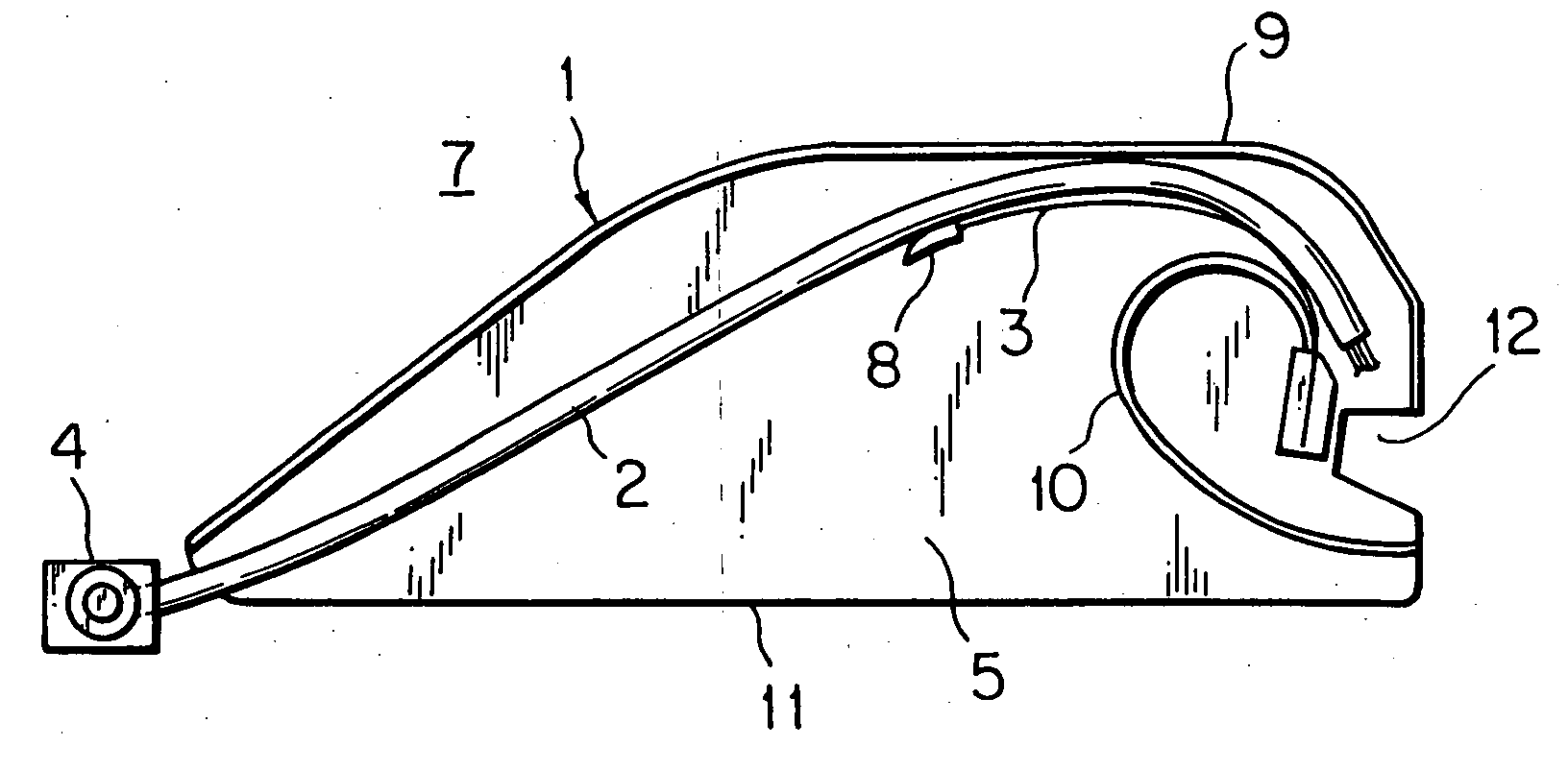
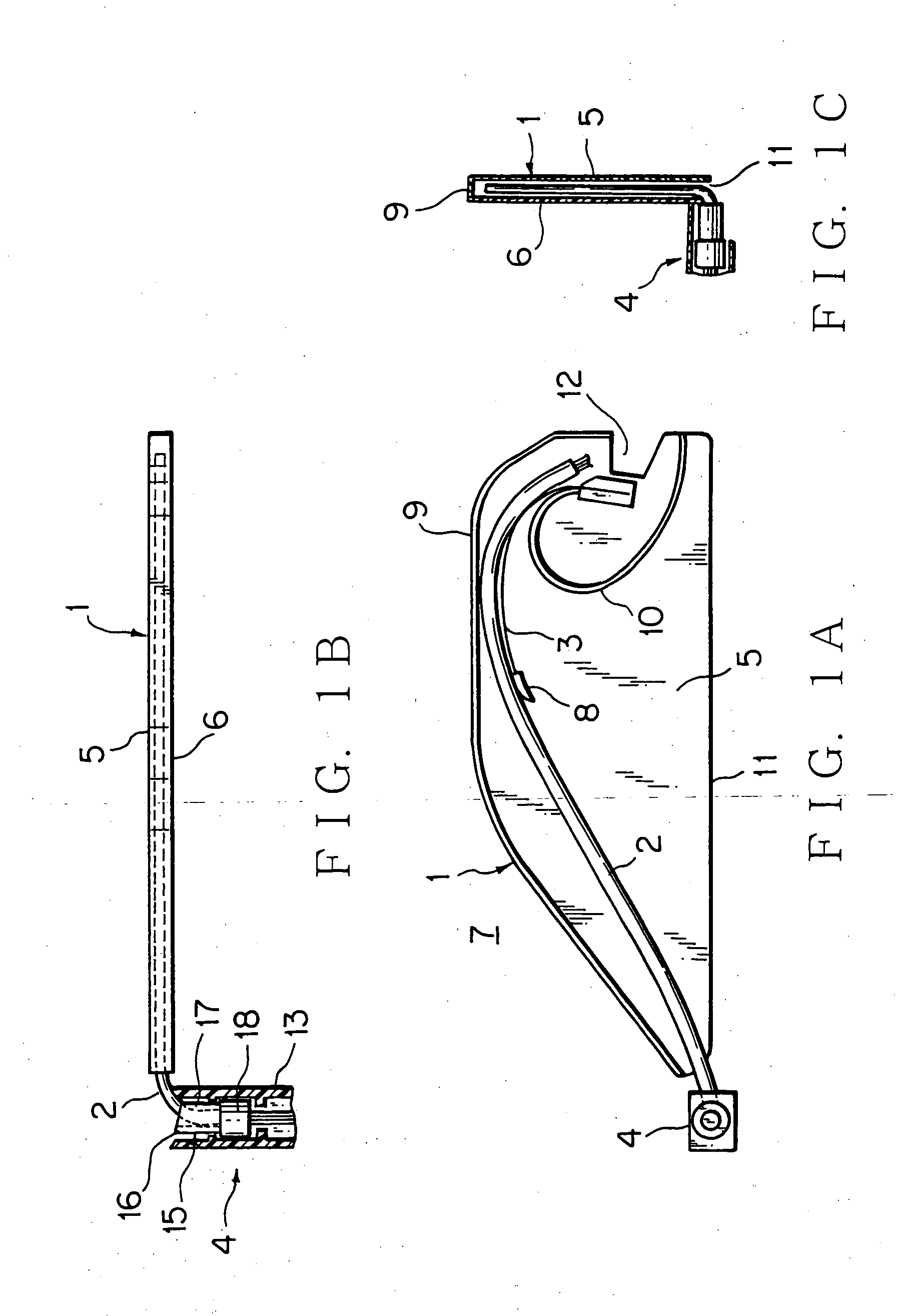
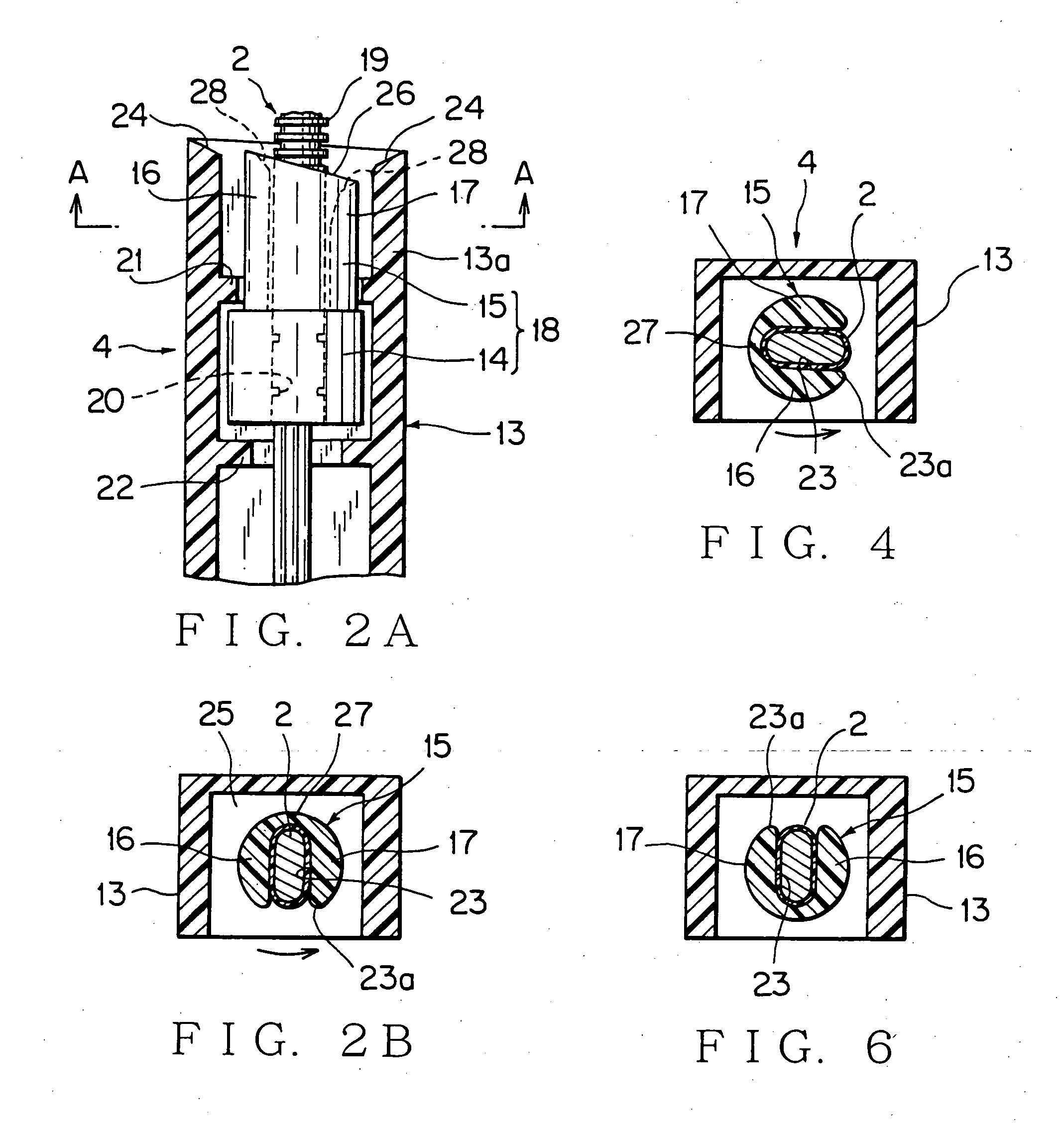
[0069]FIG. 1A, 1B, 1C show a first embodiment of a harness layout structure by using a harness holder according to the present invention. FIG. 2A, 2B show a first embodiment of the harness holder according to the present invention.

[0070] In FIGS. 1A, 1B and 1C, the mark 1 shows a synthetic resin harness protector (call protector hereafter) and the mark 2 shows a wire harness, and the mark 3 shows a flat spring (elastic member), and the mark 4 shows a harness holder.

[0071] The protector 1 includes a base 5 and a cover 6 (FIG. 1C) A power supply unit 7 includes the protector land the flat spring 3. The protector 1 is designed to have low total height. The protector 1 is disposed vertically between a metal panel of a slide door (not shown) and a resin trim. A base portion of the flat spring 3 is fixed at a front end of the base 5. A top end of the flat spring 3 supports the wire harness with pushing it upwardly through a resin cap 8.

[0072] The wire harness 2 is curved with a large r...


PUM


Abstract

For preventing slack of a wire harness and bending the wire harness more smoothly, a harness holder 71 includes an inner clamp member 31 for supporting the wire harness 73 and an outer clamp member 38 supporting rotatably the inner clamp member. The slack preventing member 35 is formed longer than the harness guide 62 in a harness leading direction. Mounting the harness holder 71 at a vehicle body and disposing a protector for receiving the wire harness 73 at a slide door, the wire harness is wired from the harness holder to the protector. In partially opened slide door, the slack preventing member 35 supports the wire harness. In full opened and completely closed door, the harness guide 62 supports the wire harness.

Description

[0001] The priority application Number Japan Patent Application Laid Open 2003-328123 upon which this patent application is based is hereby incorporated by reference. BACKGROUND OF THE INVENTION [0002] 1. Field of the Invention [0003] This invention relates to a harness holder for wiring a wire harness without a twist from a vehicle body to a slide door to supply electric power continuously, and a harness layout structure by using the harness holder. [0004] 2. Description of the Related Art [0005]FIG. 17, 18 show an example of a harness layout structure of a slide door by prior art (refer a patent document 1). [0006] In the structure, a harness protector 42 (a cover is not shown) is provided at a slide door 41 of a car, and a wire harness 43 pushed upwardly by a flat spring 44 is received freely to be flexed in the protector. One end of the wire harness 43 is led out from a front area of the protector 42 and connected with an auxiliary device at the slide door. The other end of the ...

Claims


Application Information

Patent Timeline
IPC IPC(8): B60R16/02F16B2/08H02G3/04H02G3/30H02G11/00
CPCB60R16/0215H02G11/006H02G3/34H02G3/0462
Inventor SEKINO, TSUKASATSUNODA, MITSUNORIMURAKAMI, TOMOYASUITO, GAKU
Owner YAZAKI CORP
Why Eureka
Try Eureka