Loop coilantenna

Inactive Publication Date: 2005-05-05
ORMON CORP
View PDF5 Cites 190 Cited by
  • Summary
  • Abstract
  • Description
  • Claims
  • Application Information

AI Technical Summary

Benefits of technology

[0013] An object of this invention is to provide a loop coil antenna able to dissolve the communication defect area and stably maintain the communication distance by constructing the antenna ma

Problems solved by technology

However, it is necessary to relate constant distance and direction with high accuracy between the bar code information and the bar code reader in order to read the bar code information using the bar code reader on which becomes an obstacle in the automatization and smoothing of the collation.
Further, the amount of information able to be inputted to the bar code is small, and the managing ability of the article is limited.
In this case, mismatching occurs in the antenna matching circuit 81.
However, a problem with the adjusted circ

Method used


Image

  • Loop coilantenna
  • Loop coilantenna
  • Loop coilantenna

Examples


Embodiment Construction

[0033] The embodiments of this invention will next be explained in conjunction with the drawings.

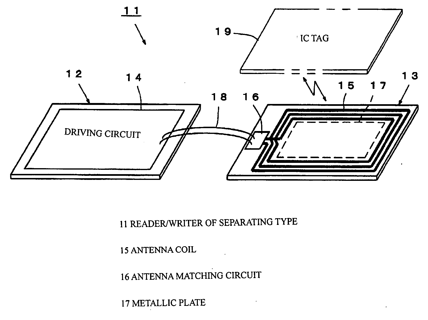
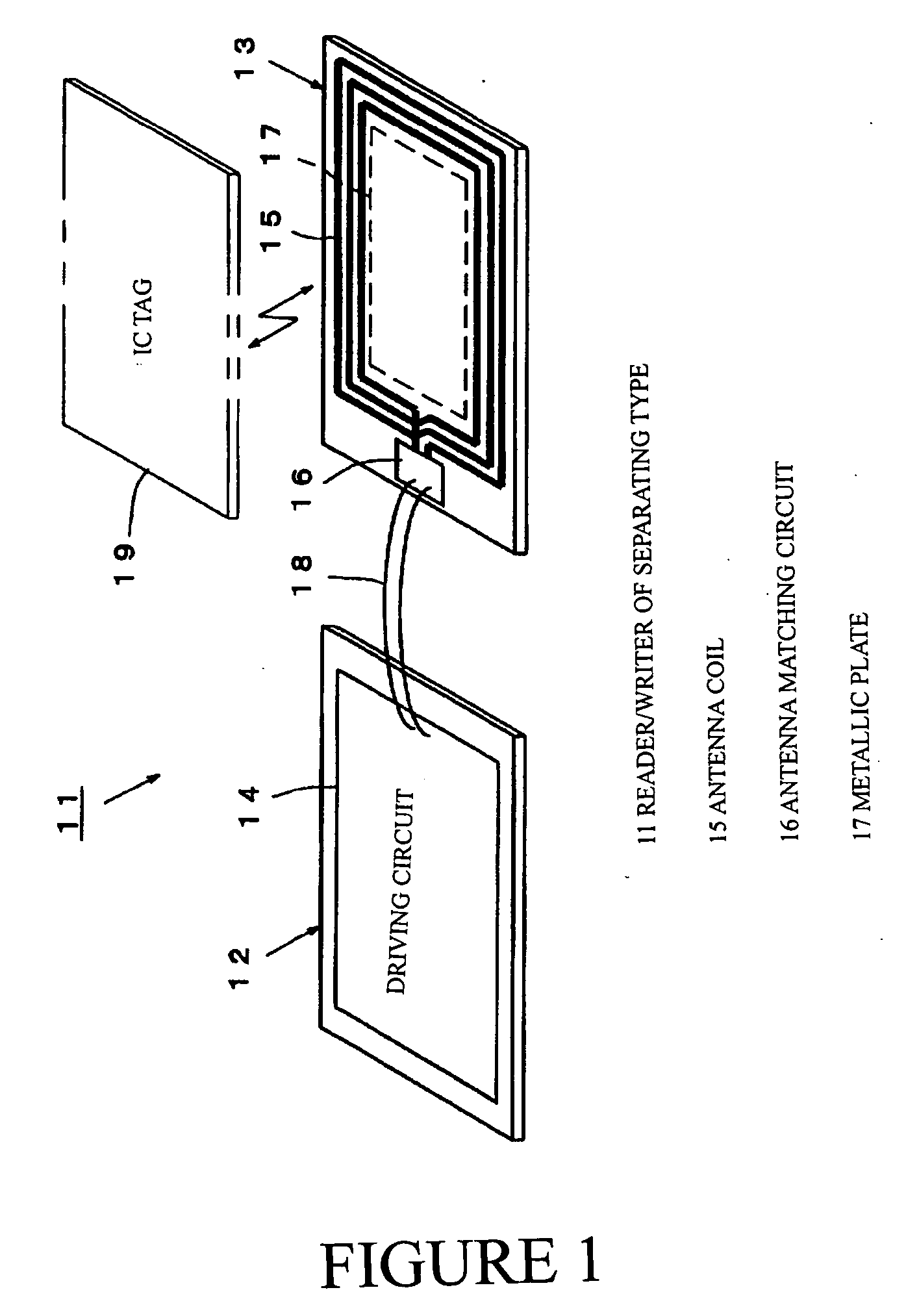
[0034]FIG. 1 shows a reader / writer of a separating type used in the RFID system. In FIG. 1, this reader / writer 11 of the separating type is arranged by separating a reader / writer substrate 12 and an antenna substrate 13, both made using a resin material being non-electrically-conductive.

[0035] A driving circuit 14 for reading and writing information is mounted to the reader / writer substrate 12. An antenna coil 15 constructed as a loop coil antenna, an antenna matching circuit 16 and an electrically conductive metallic plate 17 are mounted and arranged in the antenna substrate 13. Wiring 18 is connected between the reader / writer substrate 12 and the antenna substrate 13.

[0036] When a magnetic field is generated in the antenna coil 15 from the above reader / writer 11 and an approaching IC tag 19 enters this magnetic field generating area, an unillustrated control circuit of the IC tag 19...


PUM


Abstract

This invention constructs an antenna matching circuit able to avoid a bad influence when a conductor, such as a metal, or tag, approaches a reader/writer, and dissolves a communication defect area on the reader/writer and stably maintains a communication distance. In this invention, in a RFID system, when the tag corresponds to the generating area of a magnetic field of the reader/writer, a radio wave for sending information to the reader/writer is outputted by operating a control circuit of the tag by electric power generated in an antenna coil of this corresponding tag. A conductor is arranged near the antenna coil of the reader/writer and an eddy current is intentionally flowed. Thus, the communication defect between the reader/writer and the tag approaching this reader/writer is reduced.

Description

BACKGROUND OF THE INVENTION [0001] 1. Field of the Invention [0002] This invention relates to a RFID system (Radio Frequency Identification System) for sending and receiving information without contact by using an induced electromagnetic field between a reader / writer and a tag, and more particularly relates to a loop coil antenna able to simplify a circuit and an antenna in addition to improving communication performance. [0003] 2. Background Art [0004] It is generally important to efficiently read authentication information recorded to the tag attached to e.g., an article, to advance automatization using collation confirmation, etc. of the article and a device. A bar code corresponding to the authentication information is recorded on the tag and is read by a bar code reader to access the information. [0005] However, it is necessary to relate constant distance and direction with high accuracy between the bar code information and the bar code reader in order to read the bar code info...

Claims


Application Information

Patent Timeline
IPC IPC(8): G06K17/00G06K7/08G06K19/077H01Q1/22H01Q1/24H01Q7/00H04B1/59H04B5/02
CPCG06K7/10316G06K7/10336H01Q7/00H01Q1/2216H01Q1/22
Inventor KUDO, KAZUHIRO
Owner ORMON CORP
Why Eureka
Try Eureka