Rotor, method of manufacturing the same and rotary machine

a technology of rotating motors and rotors, applied in the field of rotating motors, can solve the problems of low productivity of magnets comprising rear-earth elements, and the lowest productivity of magnets, and achieve the effects of reducing the amount of material used for magnets and reducing the deformation of sinusoidal waveforms in the surface magnetic flux density distribution

Inactive Publication Date: 2005-05-05
KOMURO MATAHIRO +5
View PDF10 Cites 16 Cited by
  • Summary
  • Abstract
  • Description
  • Claims
  • Application Information

AI Technical Summary

Benefits of technology

[0007] The rotor is mainly composed of magnets, a shaft, a magnet fixing agent (a bonding agent or a supporting material) and magnetic steel sheets. Among the above parts and materials, the magnet is the lowest in productivity, and the productivity of a magnet comprising a rear-earth element is particularly low. Therefore, reduction of the magnet volume results in improvement of the productivity of the rotor or the motor. In addition, by reducing the volume of magnets and by using a material having a small specific gravity between the magnets, the weight of the rotor can be reduced.
[0009] An object of the present invention is to provide a rotor which has a high induced voltage characteristic and a low cogging torque characteristic and can reduce the magnet volume smaller than the magnet volume of a ring-shaped magnet of one piece, and also to provide a method of manufacturing the rotor and a rotary machine using the rotor.
[0016] That is, in the present invention, magnetization of the arc segment-shaped magnets continuously varies in the circumferential direction. By making the magnetized directions continuously vary in a sinusoidal waveform, the distribution of magnetic flux densities on the surface of the rotor also become a nearly sinusoidal waveform. Therefore, it is possible to provide a rotor in which the magnetized directions of the magnet vary in a sinusoidal waveform in the circumferential direction inside the magnet, the magnetic flux densities on the surface of the magnet showing a sinusoidal waveform distribution, the magnet volume of the arc segment-shaped magnets with the sinusoidal waveform distribution of magnetization being limited to a small amount, and the productivity being high, desirable motor characteristics being ensured.
[0018] In the case of the magnetization of the near sinusoidal waveform, the angular dependence of the surface magnetic flux density becomes as shown in FIG. 8 which is to be described later. That is, FIG. 8 shows a measured result of a magnetic flux density distribution in the radial direction on the magnet surface for two pole portions, and the waveform is near sinusoidal. By optimizing the magnetized condition, the waveform deformation from the sinusoidal waveform in the surface magnetic flux density distribution can be reduced. In the case of the magnetization of such a near sinusoidal waveform (the waveform deformation smaller than about 20%), a surface magnetic flux density higher than that in the radial ring magnet which is shaped in ring, and is magnetized in a radial direction or has magnetic anisotropy can be obtained. Therefore, by using the segmented magnets magnetized in the near sinusoidal waveform, the amount of a material used for the magnets can be reduced while the surface magnetic flux density equal to or higher than that of the radial ring-shaped magnet is being kept.

Problems solved by technology

Among the above parts and materials, the magnet is the lowest in productivity, and the productivity of a magnet comprising a rear-earth element is particularly low.

Method used


Image

  • Rotor, method of manufacturing the same and rotary machine
  • Rotor, method of manufacturing the same and rotary machine
  • Rotor, method of manufacturing the same and rotary machine

Examples


Embodiment Construction

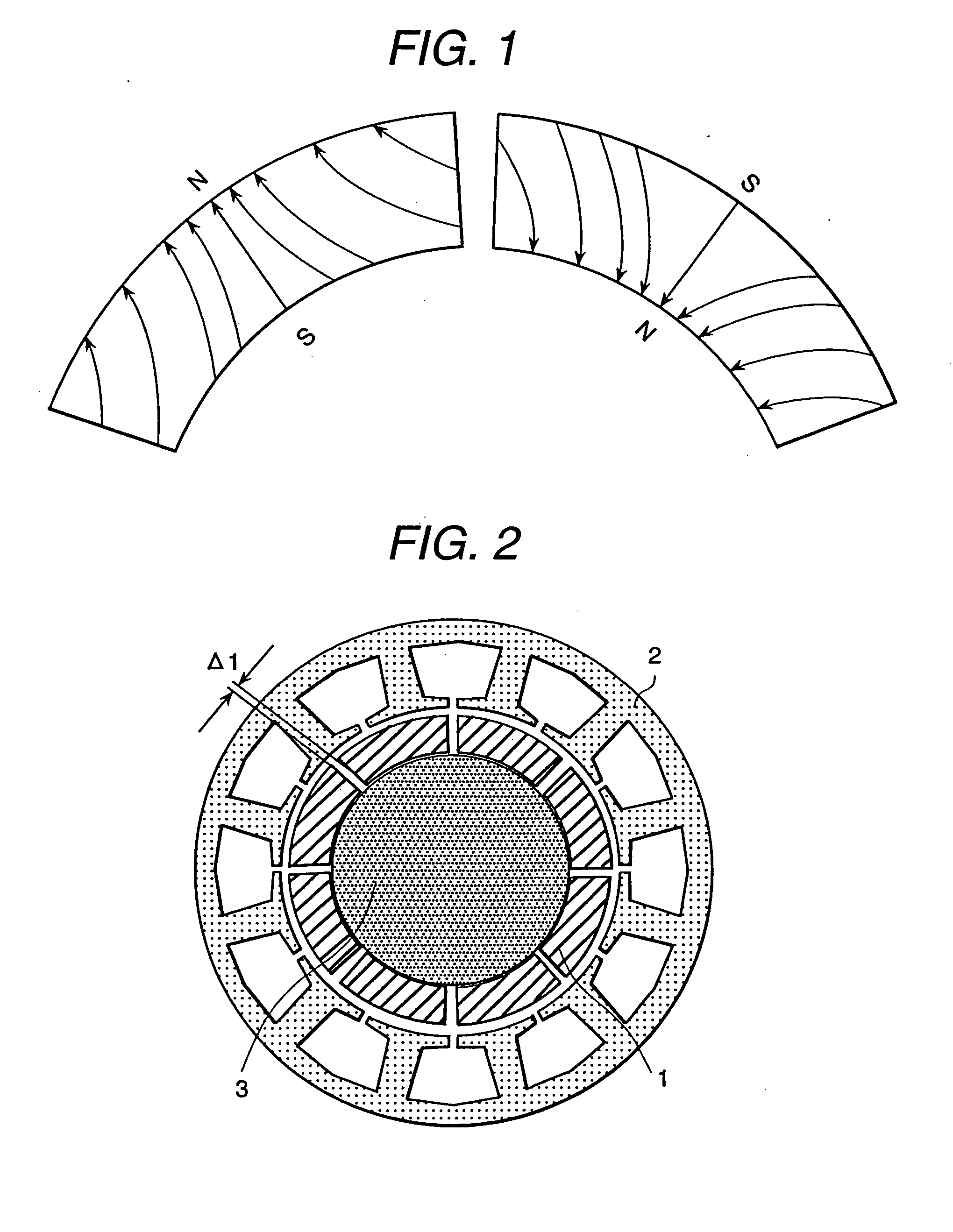
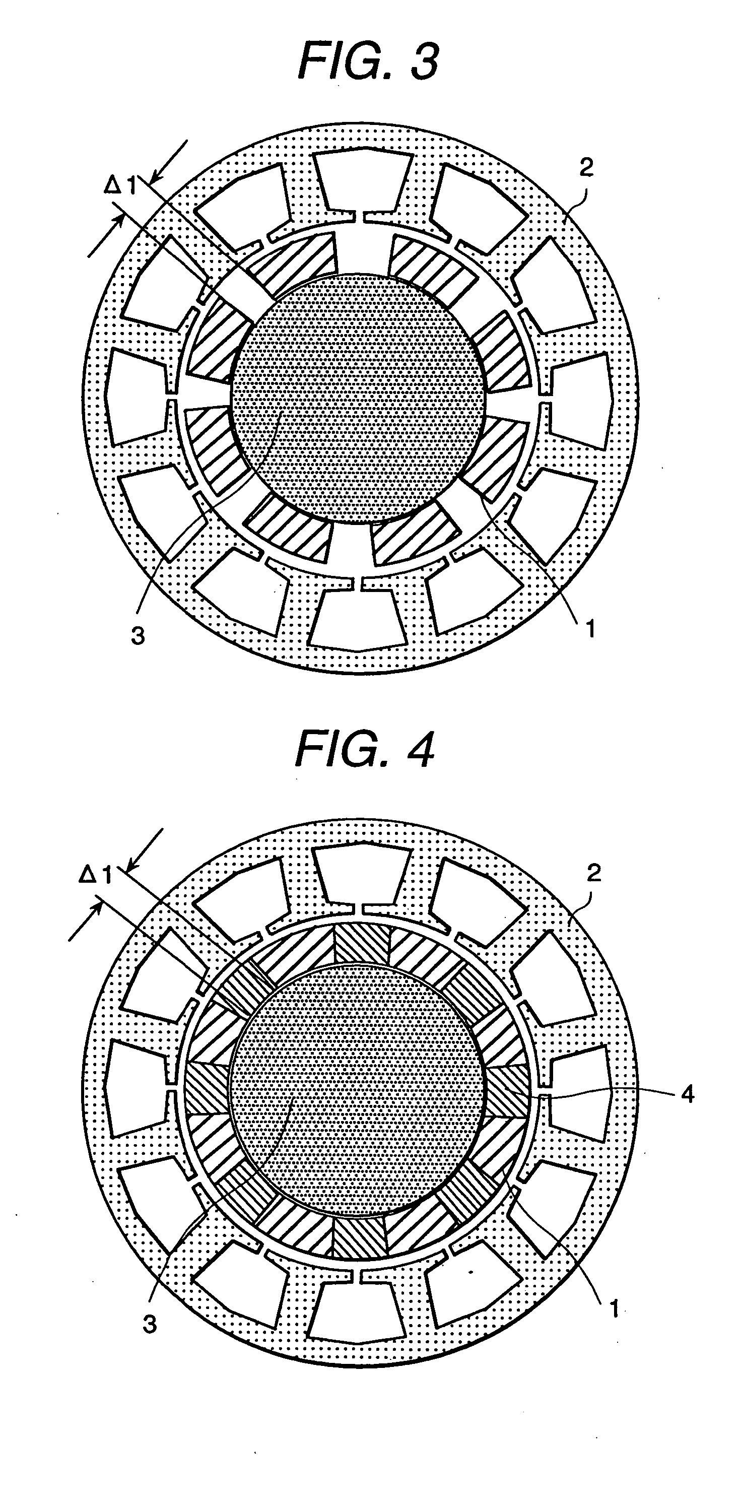
[0030]FIG. 2 is a cross-sectional view showing a rotor in accordance with the present invention. The number of poles should be two poles or more. FIG. 2 shows a case of 8 poles, and a ratio of (inner diameter) / (outer diameter) is 0.7 to 0.8. A magnet is segmented in the circumferential direction, and one segment of the magnet corresponds to one pole. A rotor shaft 3 is machined, and the surface of the rotor shaft is cleaned and applied with an adhesive. Then the segmented magnets 1 are fixed onto the rotor. In regard to magnetization of the magnets, there are a method in which the magnets magnetized before bonding are bonded onto the rotor shaft 3 and a method in which non-magnetized segmented magnets are bonded onto the rotor shaft 3 and then magnetized. Either of the above methods may be employed. After assembling the rotor, the rotor is set in the center of a stator 2. In the present embodiment, there exists a gap Δ1 in the circumferential direction between the segmented magnets....


PUM

PropertyMeasurementUnit
temperatureaaaaaaaaaa
saturation magnetic flux densityaaaaaaaaaa

Abstract

A rotor has magnets segmented in a circumferential direction of a periphery of a shaft, wherein magnetizing directions of the segmented magnets continuously vary, and a non-magnetic material or a ferromagnetic material is interposed in a circumferential gap between the segmented magnets. Further, a method of manufacturing a rotor comprises steps of arranging coils so that a longitudinal direction of each of the coils is along an axis of the shaft and magnetizing the segmented magnets. Still further, a rotary machine uses the rotor.

Description

BACKGROUND OF THE INVENTION [0001] 1. Field of the Invention [0002] The present invention relates to a novel rotor for a motor using a rotor having magnets arranged in the outer periphery of the rotating shaft, a method of manufacturing the rotor and a rotary machine. [0003] 2. Description of Prior Art [0004] Japanese Patent Application Laid-Open No. 7-336916 discloses an example in which the direction of magnetization of a magnet is continuously varied in the circumferential direction and the divided magnets are arranged in the circumferential direction. In this gazette, it is described that in regard to a hollow shaft motor, the bore diameter of the shaft bore can be made large by employing polar anisotropic magnets. Further, the gazette also shows that the N-pole segments and the S-pole segments are alternately arranged in the circumferential direction of the outer periphery of a cylindrical yoke so as to attract one another. SUMMARY OF THE INVENTION [0005] When the segment-shape...

Claims


Application Information

Patent Timeline
Patent Type & Authority Applications(United States)
IPC IPC(8): H02K21/14C12M3/06H02K1/27H02K15/03
CPCH02K15/03H02K1/278
Inventor KOMURO, MATAHIROKITAMURA, MASASHIKANEDA, JUNYAITO, MOTOYAABE, TERUYOSHIKURIYAMA, YOSHIHIKO
Owner KOMURO MATAHIRO
Why Eureka
Try Eureka