Confocal microscope comprising two microlens arrays and a pinhole diaphragm array

a technology of pinhole diaphragm array and microlens array, which is applied in the field of confocal microscope with microlens array, can solve the problems of comparatively insensitive arrangement of both microlens arrays in the new confocal microscope, and achieve the effect of reducing the effective diaphragm aperture of the pinhole diaphragm array, reducing the size of the common passageway cross-section, and maximizing the diaphragm apertur

Inactive Publication Date: 2005-05-05
MAX PLANCK GESELLSCHAFT ZUR FOERDERUNG DER WISSENSCHAFTEN EV
View PDF4 Cites 46 Cited by
  • Summary
  • Abstract
  • Description
  • Claims
  • Application Information

AI Technical Summary

Benefits of technology

[0015] To vary the effective size of the aperture of the pinhole diaphragms of the pinhole diaphragm array, a further diaphragm array corresponding to the first diaphragm array may be provided, which is arranged directly in front of or behind the first diaphragm array and which may be moved in parallel to the first diaphragm array. The maximum size of the common passageway cross-section of both pinhole diaphragm arrays is given when the pinhole diaphragm arrays coincide. Upon increasing movement with regard to each other, the size of the common passageway cross-section decreases so that the effective diaphragm aperture of the pinhole diaphragms of the pinhole diaphragm arrays decreases. For example, the diaphragm aperture may be maximized, when the new confocal microscope is used for a two-photon-ex

Problems solved by technology

The arrangement of both microlens arrays in the new confocal microscope is comp

Method used


Image

  • Confocal microscope comprising two microlens arrays and a pinhole diaphragm array
  • Confocal microscope comprising two microlens arrays and a pinhole diaphragm array
  • Confocal microscope comprising two microlens arrays and a pinhole diaphragm array

Examples


Embodiment Construction

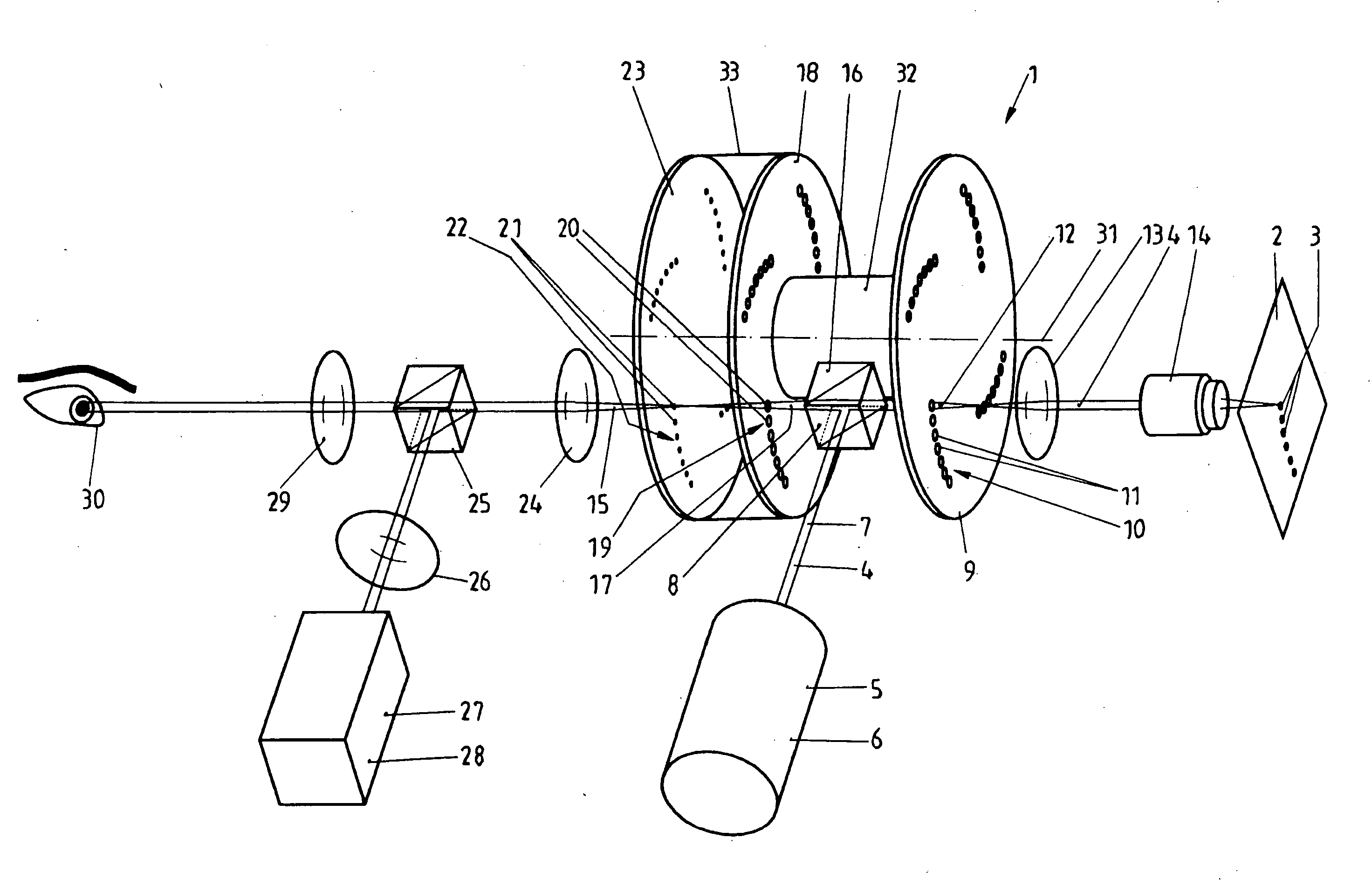
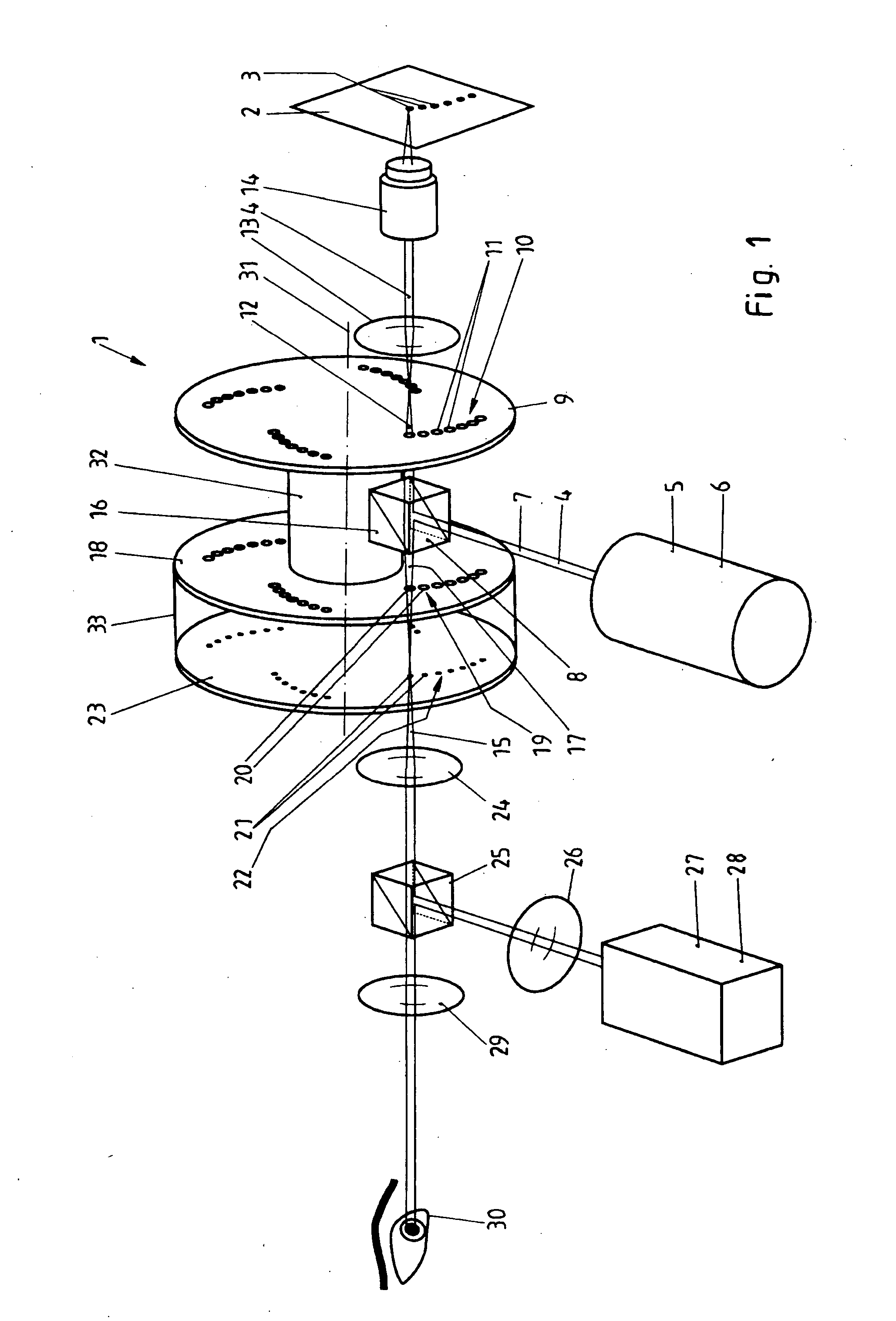
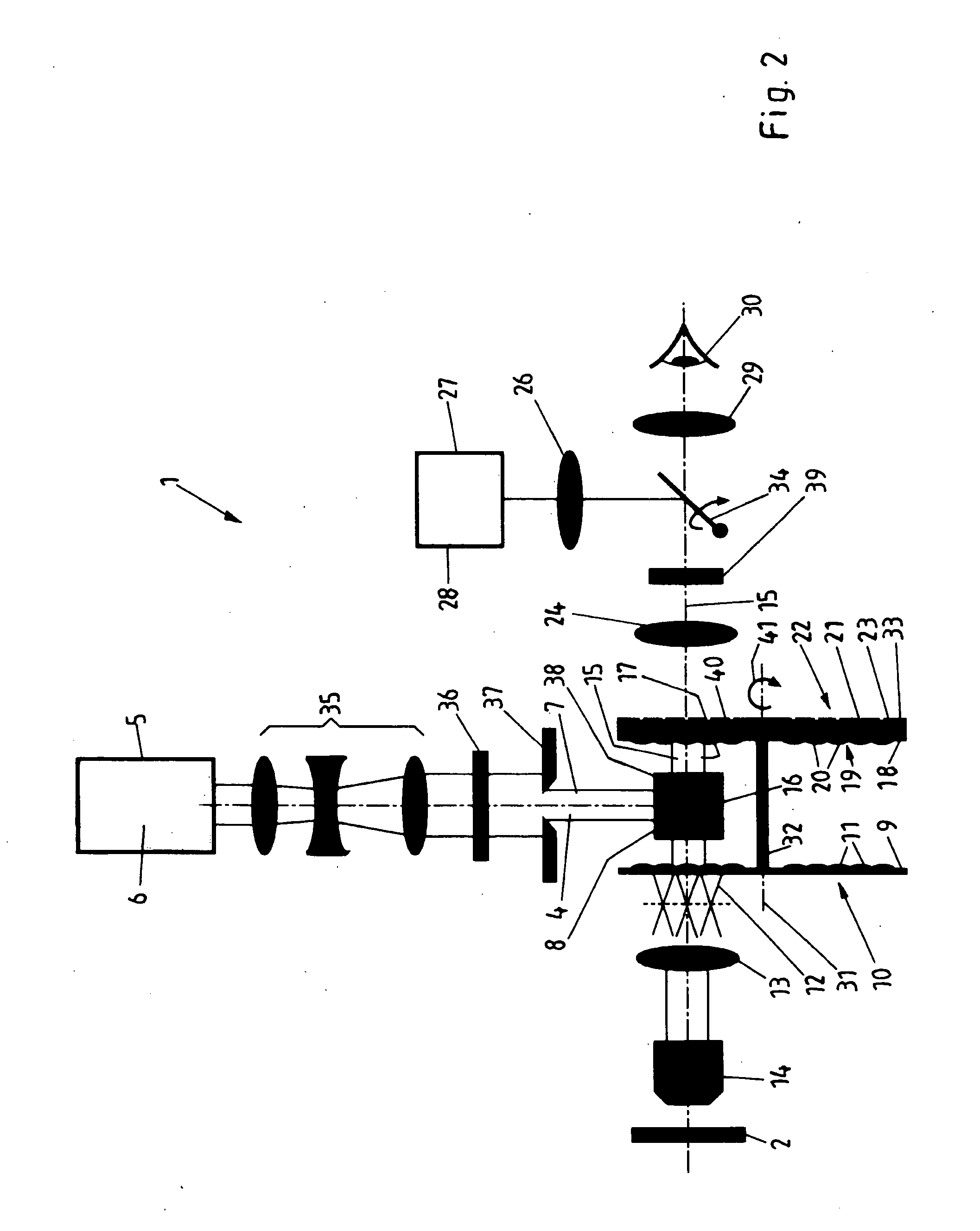
[0028]FIG. 1 shows the basic construction of a confocal microscope 1 for simultaneously measuring a sample 2 in a plurality of measuring points 3. In each of the measuring points, the sample 2 is illuminated by illumination light 4. The illumination light 4 comes from a light source 5 typically being a laser 6. The illumination light coming from the laser 6 is a parallel ray bundle 7. The parallel ray bundle 7 is deviated by a beam splitter 8 towards a microlens wheel 9. The microlens wheel 9 has a microlens array 10 consisting of a plurality of microlenses 11 arranged side by side. The microlens array 10 splits the ray bundle 7 into a plurality of convergent partial ray bundles 12 only one of which being depicted here. Via a tube lens 13 and a microscope objective 14 each partial ray bundle 12 is focussed in one of the measuring points 3. The tube lens 13 and the microscope objective 14 are common to all partial ray bundles 12. In the measuring points 3 the sample 2 is excited for ...


PUM


Abstract

A confocal microscope comprises a microlens array having a plurality of microlenses for splitting a ray bundle of illumination light into a plurality of convergent partial ray bundles which illuminate a sample simultaneously at several measuring points; a beam splitter for separating a beam path of the illuminating light and a beam path of sample light originating from the illumination of the sample and captured in an inverse direction with regard to the illumination light; a pinhole diaphragm array having a plurality of pinhole diaphragms arranged in the beam path of the sample light and corresponding to said microlenses of said microlens array splitting the illumination light; and a further microlens array having a plurality of microlenses corresponding to said microlenses of said microlens array splitting the illumination light. Said microlenses of said microlens array splitting the illumination light and said microlenses of said further microlens array are arranged in the beam path of the sample light. Said beam splitter is arranged in an area between said microlens array splitting the illumination light and said further microlens array; and said pinhole diaphragms of said pinhole diaphragm array are not arranged in the area between said microlens array splitting the illumination light and said further microlens array.

Description

CROSS REFERENCE TO RELATED APPLICATIONS [0001] This application is a continuation of International Patent Application PCT / EP03 / 04470 filed Apr. 29, 2003 and claiming priority to co-pending European Patent Application No. 02009913.1 filed May 3, 2002, both of which are entitled “Konfokales Mikroskop mit zwei Mikrolinsenarrays und einem Lochblendenarray”.FIELD OF THE INVENTION [0002] The invention relates to a confocal microscope with a microlens array for splitting a ray bundle of illumination light into a plurality of convergent partial ray bundles, in order to illuminate a sample simultaneously at several measuring points, a beam splitter for separating the beam path of the illumination light and of the sample light originating from the illumination of the sample and captured in an inverse direction with regard to the illumination light, and a pinhole diaphragm array in the beam path of the sample light which corresponds to the microlens array for splitting the illumination light. ...

Claims


Application Information

Patent Timeline
IPC IPC(8): G02B21/00
CPCG02B21/0044G02B21/0032
Inventor HELL, STEFANPICK, RAINER
Owner MAX PLANCK GESELLSCHAFT ZUR FOERDERUNG DER WISSENSCHAFTEN EV
Why Eureka
Try Eureka