
Recording method for a phase change optical disc

Inactive Publication Date: 2005-05-05
LG ELECTRONICS INC
View PDF13 Cites 5 Cited by
  • Summary
  • Abstract
  • Description
  • Claims
  • Application Information

AI Technical Summary

Benefits of technology

[0014] In view of the shortcomings of the prior art, it is an object of the present invention to provide a recording method for a rewritable phase change optical disk such as CD-RW, DVD-RW, and BD-RE that is capable of improving recording and playback characteristics.
[0015] It is an object of the present invention to provide a recording method for a rewritable phase change optical disk that prevents crystalline material from growing at the leading portion of predetermined marks, e.g. marks 4T or more in length due to the heat from multi pulses.
[0016] It is yet another object of the present invention to provide a recording method for a rewritable phase change optical disk that reduces or prevents the inequalities in the beginning positions of marks 2T and 3T in length and marks more than 4T in length resulting from the increase in the interval-between the first pulse and multi pulses for forming marks 4T or more in length.
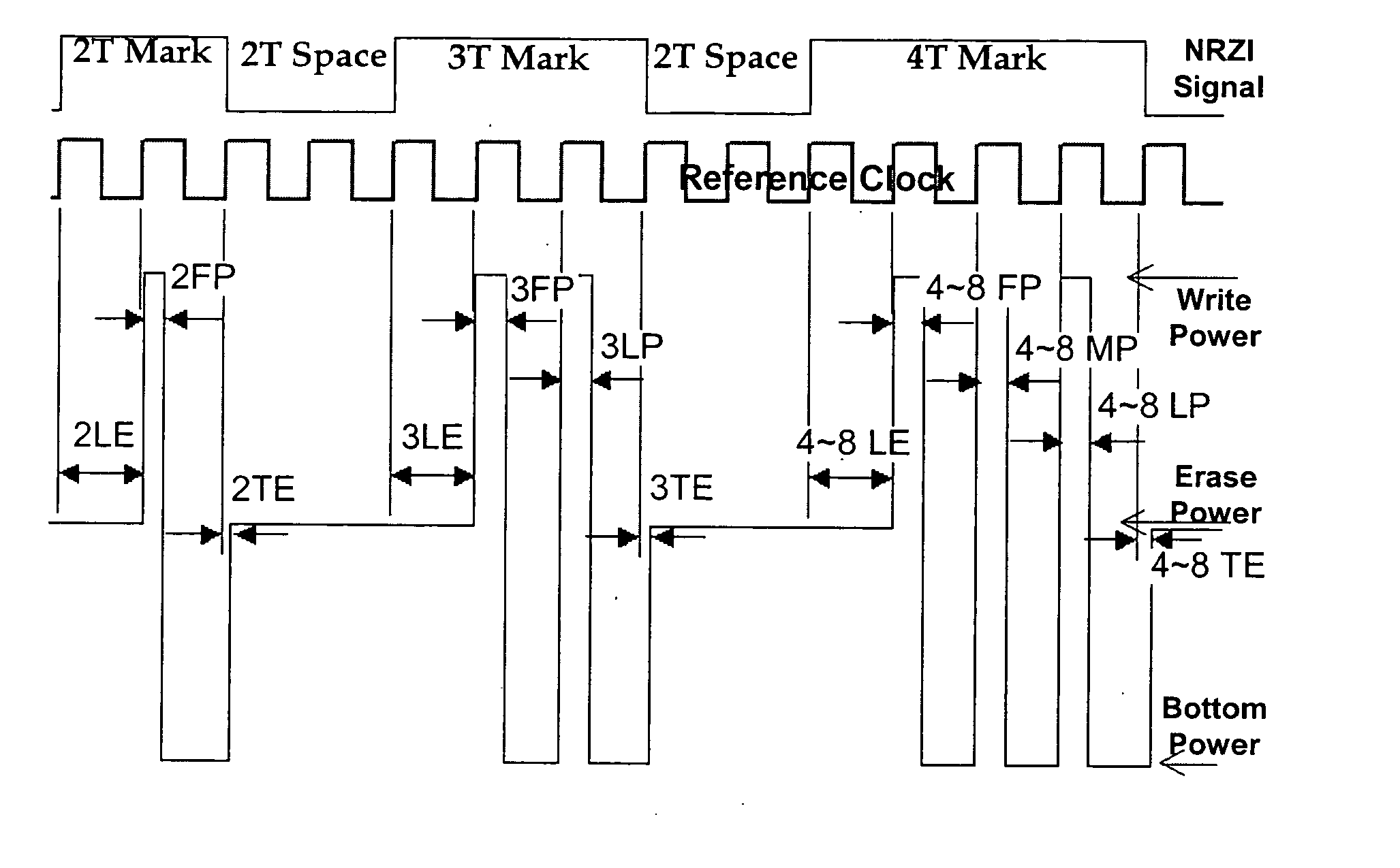
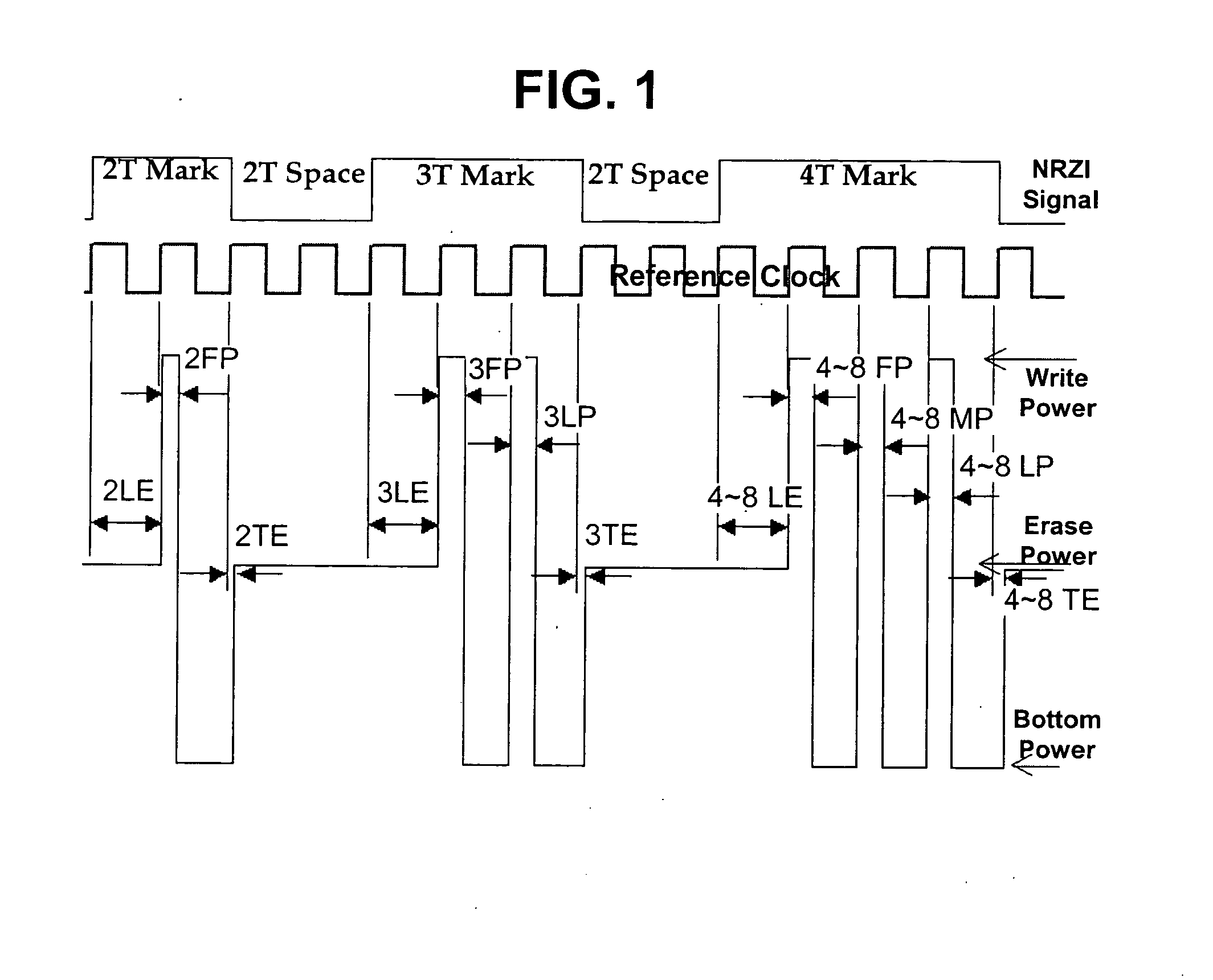
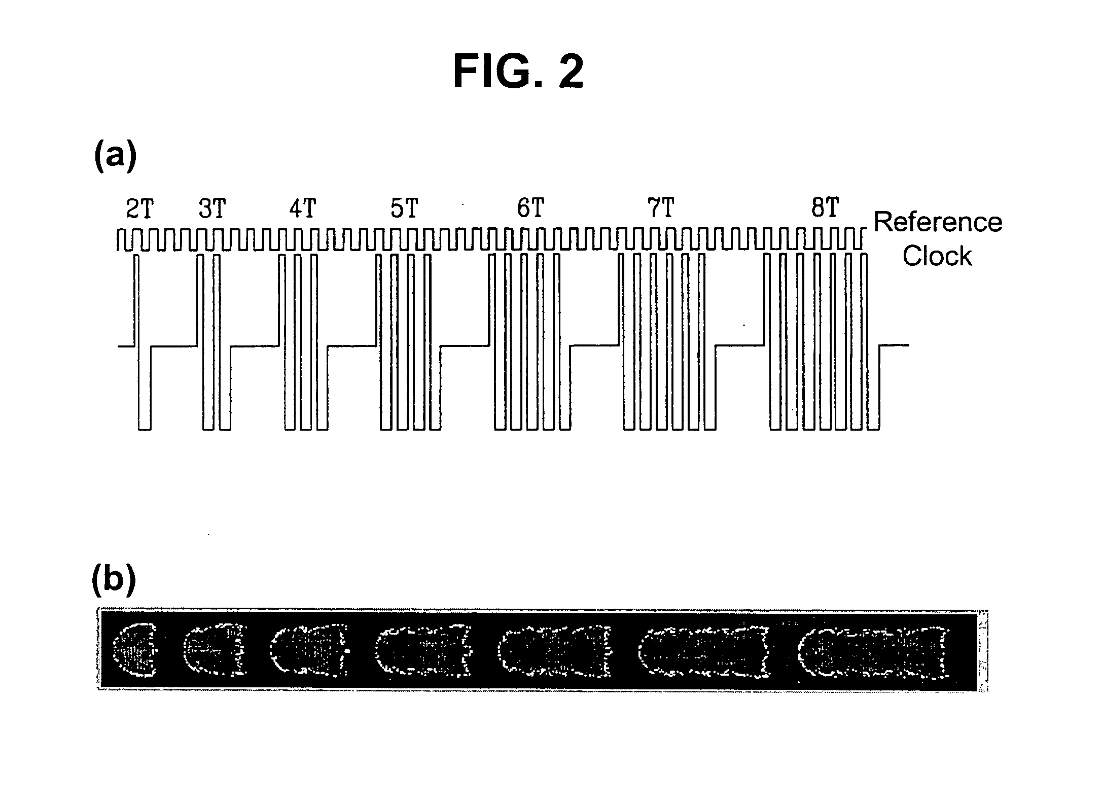
[0017] In one embodiment of the present invention, the interval between a first pulse and multi pulses among write pulses for forming predetermined marks, e.g. marks 4T or more in length is increased within a predefined limit by delaying the leading pulse or all of the multi pulses. Alternatively, the interval between the first pulse and multi pulses can be increased by advancing the first pulse and last pulse among write pulses for forming marks 2T or more in length with multi pulses among write pulses for forming 4T or more in length unchanged. Increasing the interval between the first pulse and multi pluses among write pulses for forming marks 4T or more in length prevents crystalline material from growing at the leading portion of marks 4T or more in length due to the heat from multi pulses. In this case, the widths or levels of the multi pulses are increased to reduce the formation of a neck shape that would be formed at the leading portion of the marks due to the increase of the interval between the first pulse and the multi pulses.
[0018] In another embodiment, the inequalities in the beginning positions of marks 2T and 3T in length and marks 4T or more in length resulting from the movement of the leading portion of marks 4T˜8T in length caused by the increase of the interval between the first pulse and multi pulses among write pulses for forming marks 4T or more in length are prevented by advancing the last pulse (3LP) for 3T marks and last pulse (4LP) for marks 4T or more in length by a predefined period t. It is recommended that the predefined period does not exceed ({fraction (3 / 16)})T.

Problems solved by technology

A single laser pulse cannot form a well-shaped amorphous mark on a crystalline matrix because of accumulated heat.

Method used


Image

  • Recording method for a phase change optical disc
  • Recording method for a phase change optical disc
  • Recording method for a phase change optical disc

Examples


first embodiment

[0044] A first embodiment wherein the position of multi pulses is shifted with a view to improving the quality of RF signal generated at the leading portion of 4T˜8T marks is described.

[0045] In order to improve the reproduced signal quality, the leading portion of a mark melt by the first pulse needs to be cooled quickly to become amorphous. To this end, multi pulses following the first pulse for 4T˜8T marks are delayed as shown in FIG. 5a. Increasing the interval between the first pulse and the beginning of the multi pulses for forming 4T˜8T marks prevents the leading portion of the marks from being reheated by the multi pulses and thus increases the cooling rate of the leading portion, thereby reducing the growth of crystalline material at the leading portion, as shown in FIG. 5b.

[0046] If the NRZI signal corresponds to marks 4T˜8T in length, the LD driver 15 creates write pulses comprising leading erase power time duration (LE), first pulse (FP), multi pulses (MP), last pulse (...

second embodiment

[0056] the present invention for solving the aforementioned problem of the method that the leading portion of marks 4T or more in length moves in the opposite direction the laser beam is going on will now be described in detail.

[0057]FIG. 9a illustrates write pulses in accordance with the second embodiment and 9b illustrates a photograph of marks formed by the write pulses.

[0058] In a second embodiment of the present invention shown in FIG. 9a, the beginning of multi pulses (4MP˜8MP) for forming 4T˜8T marks is delayed so that the multi pulses start after the rising edge of the reference clock therefor and the rising edges of the last pulse (3LP) for 3T marks and last pulse (4LP) for marks 4T or more in length are advanced by a predefined period t (02T, 3T, and 4T in length formed by the write pulses is shown in FIG. 9b.

[0059] The waveform of the write pulses shown in FIG. 9a is one exemplary embodiment of the present invention and therefore the present invention is not limited to ...


PUM


Abstract

A recording method for a phase change optical disk is disclosed. To prevent crystalline material from growing at the leading portion of predetermined marks, e.g. marks 4T or more in length, the interval between the first pulse and multi pulses among write pulses for forming marks 4T or more in length is increased by delaying the multi pulses against a reference clock and the widths or levels of the multi pulses are also increased. In another embodiment, to prevent a change in the starting positions of marks due to the increase of the interval between the first pulse and multi pulses, the last pulse among write pulses for forming marks 3T or more in length is advanced by a predefined time period. In still another embodiment, the interval between the first pulse and multi pulses among write pulses for forming marks 4T or more in length is increased and the starting position of the first pulse, the starting position and width of the last pulse, a trailing edge cooling time deviation are individually adjusted depending on the length of marks.

Description

1. TECHNICAL FIELD [0001] The present invention relates to a recording method for a phase change optical disk and, more particularly, but not by way of limitation, to a method of adjusting laser write pulses for a phase change optical disk with a view to improving the quality of repeated recording. 2.BACKGROUND ART [0002] With the advent of multimedia era that deals with video data including moving or still pictures, audio data, and computer data in an integrating manner, the use of package media such as CDs and DVDs has been dramatically increased and is expected to be on this path. The standardization of new high-density optical disks such as Blu-ray Disc (BD) has been progressing rapidly and new optical disk related products are expected to be commercially available on the market in the near future. [0003] A package medium, e.g., CD, DVD, or BD, comprises a substrate, a recording layer, and a protective layer. A read-only optical disk has pre-pits formed thereon that provide serv...

Claims


Application Information

Patent Timeline
IPC IPC(8): G11B7/0045G11B7/006
CPCG11B7/0062G11B7/00454
Inventor LEE, KWANG LYULKIM, JIN HONGSEO, HUNLEE, SEUNG YOONKWAK, KEUM CHEOL
Owner LG ELECTRONICS INC
Learn More