
Methods and apparatus for tileable sensor array

a sensor array and tile technology, applied in the field of electromechanical arrays, can solve the problems of inability to scale well to the detector array, high cost and time-consuming alignment procedures,

Active Publication Date: 2005-05-05
GE MEDICAL SYST GLOBAL TECH CO LLC
View PDF8 Cites 20 Cited by
  • Summary
  • Abstract
  • Description
  • Claims
  • Application Information

AI Technical Summary

Benefits of technology

[0009] It will be recognized that configurations of the present invention facilitate insertion and extraction or field replacement of sensor arrays in a detector array with high dimensional accuracy, even without the use of special tools or extra attachment components. Furthermore, some configurations of the present invention facilitate insertion and extraction or field replacement of sensor arrays in two dimensional detector arrays. High dimensional accuracy can be achieved at relatively low cost and in high production volumes.

Problems solved by technology

Thus, alignment procedures tend to be expensive and time-consuming.
Moreover, the procedures do not scale well to detector arrays comprising two-dimensional arrays of sensor arrays, for example, three adjacent rows of over 50 sensor elements.

Method used


Image

  • Methods and apparatus for tileable sensor array
  • Methods and apparatus for tileable sensor array
  • Methods and apparatus for tileable sensor array

Examples


Embodiment Construction

[0025] As used herein, a “sensor array” refers to a component comprising one or more individual sensors. In many configurations, a sensor array may itself comprise a component having a two-dimensional array of sensors, and a plurality of sensor arrays may be assembled into a larger assembly referred to as a “detector array.” A “sensor array” may comprise an M×N array of sensors, wherein both M or N are equal to or greater than one. Thus, the scope of the term “sensor array” is not intended to exclude devices having only one sensor.

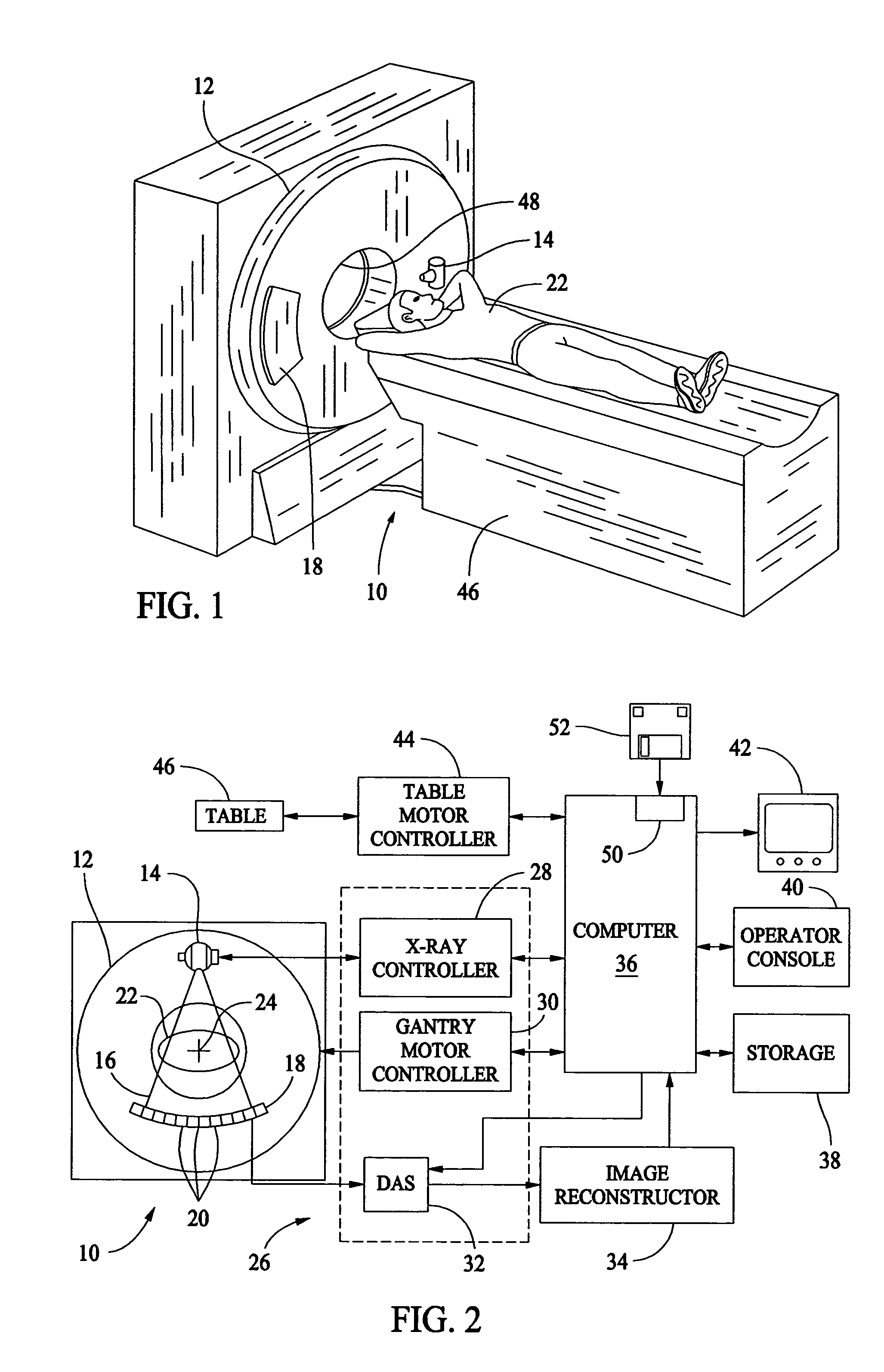
[0026] In some known CT imaging system configurations, an x-ray source projects a fan-shaped beam which is collimated to lie within an X-Y plane of a Cartesian coordinate system and generally referred to as an “imaging plane”. The x-ray beam passes through an object being imaged, such as a patient. The beam, after being attenuated by the object, impinges upon an array of radiation detectors. The intensity of the attenuated radiation beam received at the d...


PUM

PropertyMeasurementUnit
diametersaaaaaaaaaa
diametersaaaaaaaaaa
diametersaaaaaaaaaa

Abstract

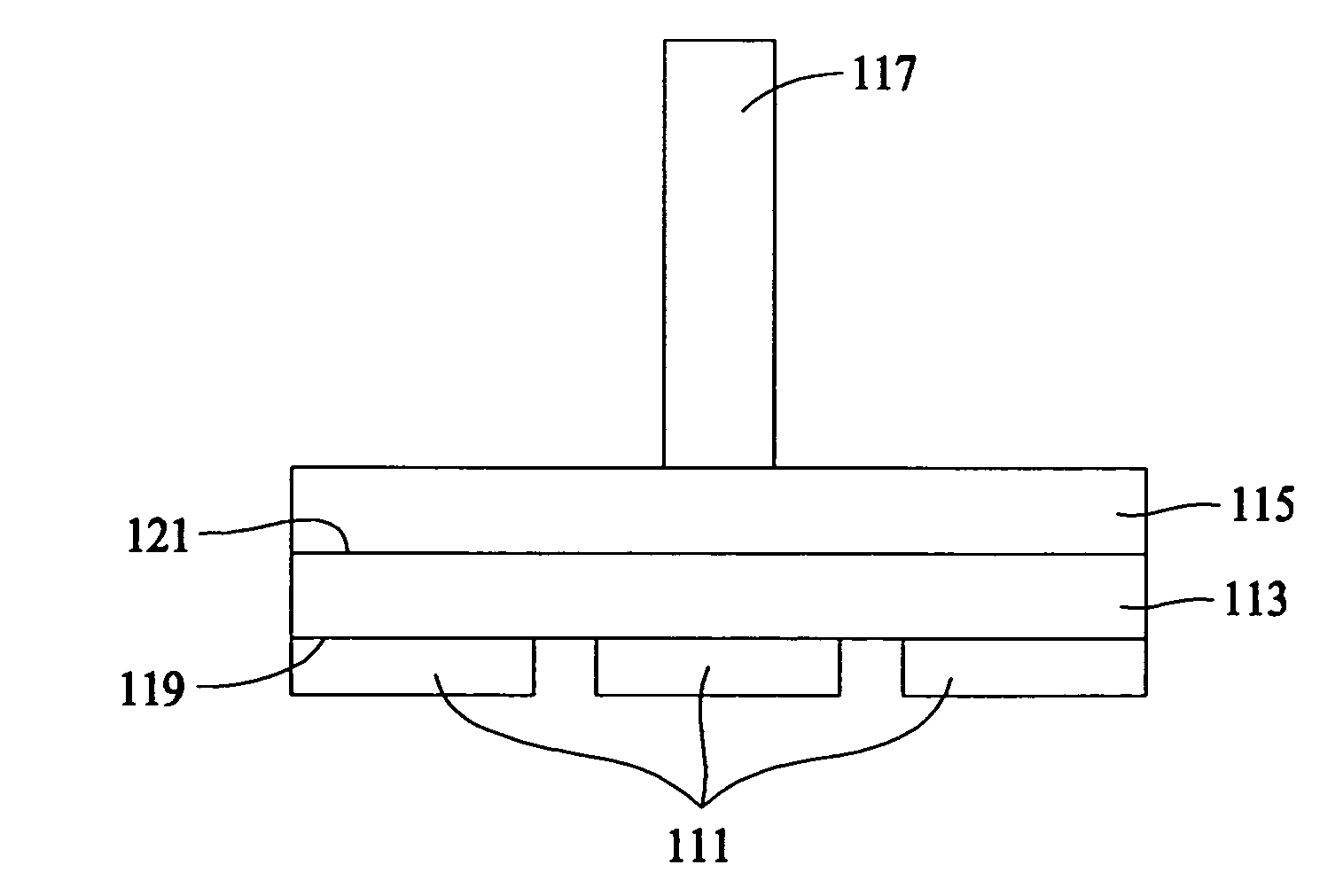
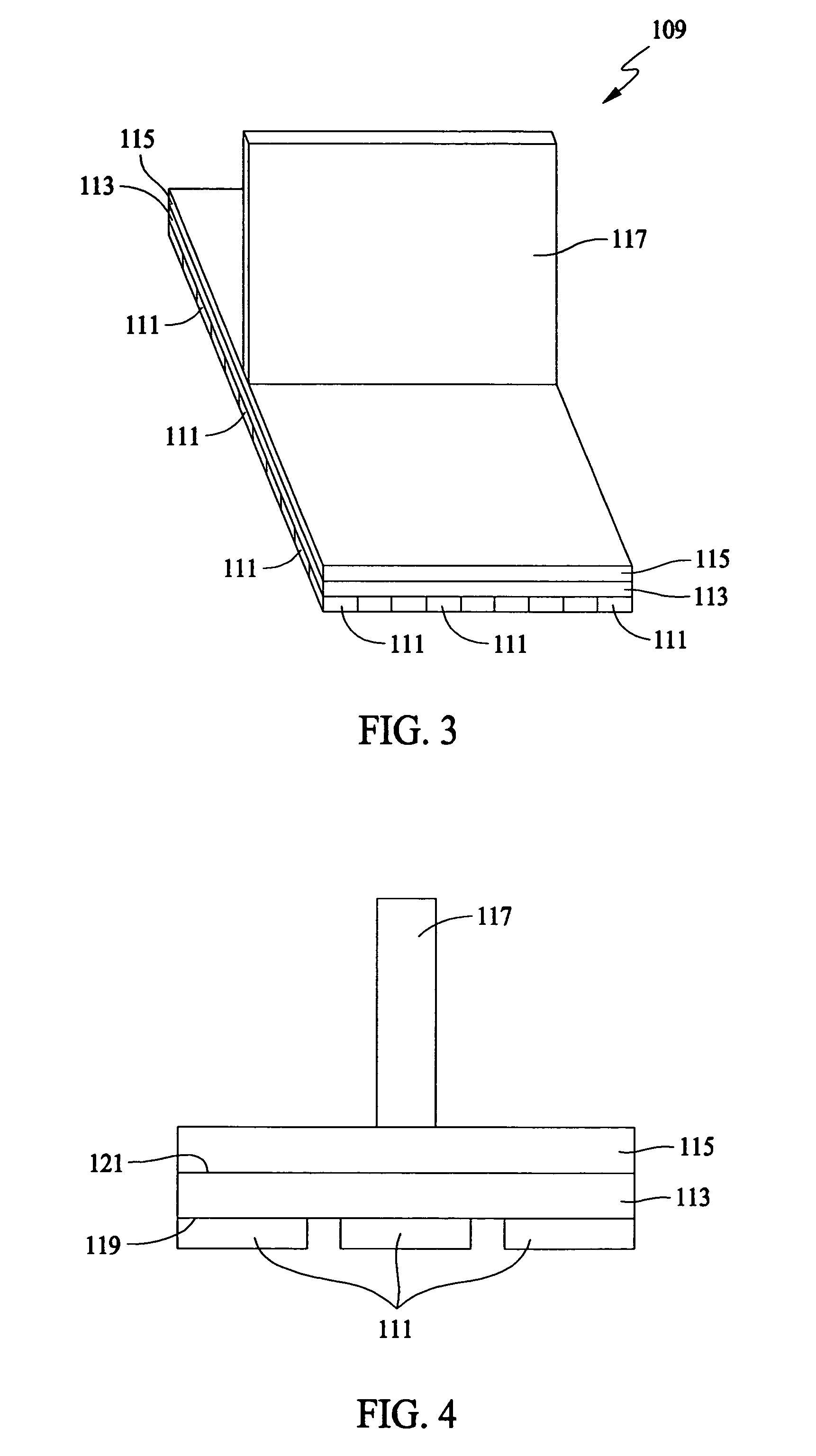
A detector array kit that includes at least one sensor array. The sensor array has an active side at least one sensor on the flat active side configured to detect a particular form of energy. The sensor array active side has a positioning structure on the active side that is essentially transparent to the particular form of energy. The positioning structure includes a plurality of spaced compressible posts or tubes configured to compressively and frictionally engage with a complementary mounting structure. The detector kit further includes a complementary mounting structure essentially transparent to the particular form of energy.

Description

BACKGROUND OF THE INVENTION [0001] This invention relates generally to electronic arrays, and more particularly, to methods and apparatus suitable for assembling accurately aligned electronic sensor arrays. [0002] Electronic sensors and transmitters are often configured in arrays to transmit or receive data in a two dimensional format or to effect a desired resolution for a given area. For example, at least one known sensor includes a photodiode including an array of photosensitive pixels coupled to a scintillating medium, which can also be configured as an array of scintillator cells. When subjected to x-ray energy, the scintillator generates optical photons which in turn excite the underlying photosensitive pixels within the photodiode thereby producing an electrical signal corresponding to an incident photon flux. [0003] Assembly of a computed tomographic (CT) detector array requires high precision alignment of more than 50 sensor elements. In at least one known system, a detecto...

Claims


Application Information

Patent Timeline
Patent Type & Authority Applications(United States)
IPC IPC(8): A61B6/00A61B6/03G01N23/00G21K1/02G21K1/12H05G1/60
CPCA61B6/032A61B6/4411G21K1/025A61B2562/046A61B2562/02
Inventor SHERMAN, DONNA MARIEBURDICK, WILLIAM EDWARD JR.ROSE, JAMES WILSON
Owner GE MEDICAL SYST GLOBAL TECH CO LLC
Learn More