Multi-level, automated vehicle parking structure

a parking structure and multi-level technology, applied in the field of multi-level, automated parking structures, can solve the problems of low steady throughput, inability to meet the needs of vehicles, etc., to solve and achieve the effect of solving the combined problems of rapid vehicle throughput and construction costs

Inactive Publication Date: 2005-05-05
SEGAL +1
View PDF12 Cites 52 Cited by
  • Summary
  • Abstract
  • Description
  • Claims
  • Application Information

AI Technical Summary

Benefits of technology

[0010] It is an object of the present invention to provide a new and improved multi-level, automated vehicle parking structure in which at least some of the disadvantages inherent in the prior art constructions are substantially reduced.
[0022] This provision of the structure with a plurality of centrally located elevatora who centre base lines are not radially directed with respect to the rotational axis of the structure and, their association with off-radially directed parking spaces on the platforms allows for a very significant economy in space in the central air shaft (as compared with the space required to accommodate radially directed elevators). This, together with the possibility of supplementing the central elevators with additional elevators disposed adjacent the outer peripheries of the rotatable platforms radically increases the vehicle throughput capacity of the styructure.
[0024] It will be appreciated that, the provision, in accordance with this aspect of the invention, of a bank of elevators within the inner periphery of the rotatable platforms and which are off-radially directed and which are designed to communicate with similarly off-radially directed parking spaces on the platforms allowsw for a maximal number of elevators in a minimal spatial region thereby considerably contributing to to an increased vehicle throughput with minimal increase of constructional space.
[0043] Such an arrangement allows for a radically increase potential for rapid and effective vehicle throughput especially during peak traffic times.

Problems solved by technology

Nevertheless, few automated parking systems have actually been installed or enjoyed financial success, possibly because of high cost but mainly due to their inability to carry out vehicle parking and retrieving rapidly and efficiently enough when many clients are waiting in line, namely their steady throughput is too low and not reliable.
The prior art contains examples of automated parking structures having successive circular, particularly annular parking levels, none of which, however, have provided a solution for the combined problems of construction costs and rapid vehicle throughput.
This structure is volume-consuming as the inner diameter of the center, devoted to vehicle transfer, is very large, because of the spatial requirements of a central structural shaft wherein a plurality of rotatable elevators are located.
The structure is not provided with any means for ensuring transfer of vehicles from one rotating platform to its coaxial neighbor.
Furthermore the location and mode of operation of the elevators do not, for example, offer any back-up provision for the eventuality that the inner elevator fails to function.
Hence the response time of the system is slow.
Also, the center shaft is dedicated to car transfer and therefore the volumetric efficiency of the system is relatively small.
This patent, like many others in the prior art, uses pallets rather than dollies for transferring and storing the vehicles which makes it dependent on a pallet handling system and additional needed space, that further reduce the throughput of such system.

Method used


Image

  • Multi-level, automated vehicle parking structure
  • Multi-level, automated vehicle parking structure
  • Multi-level, automated vehicle parking structure

Examples


first embodiment

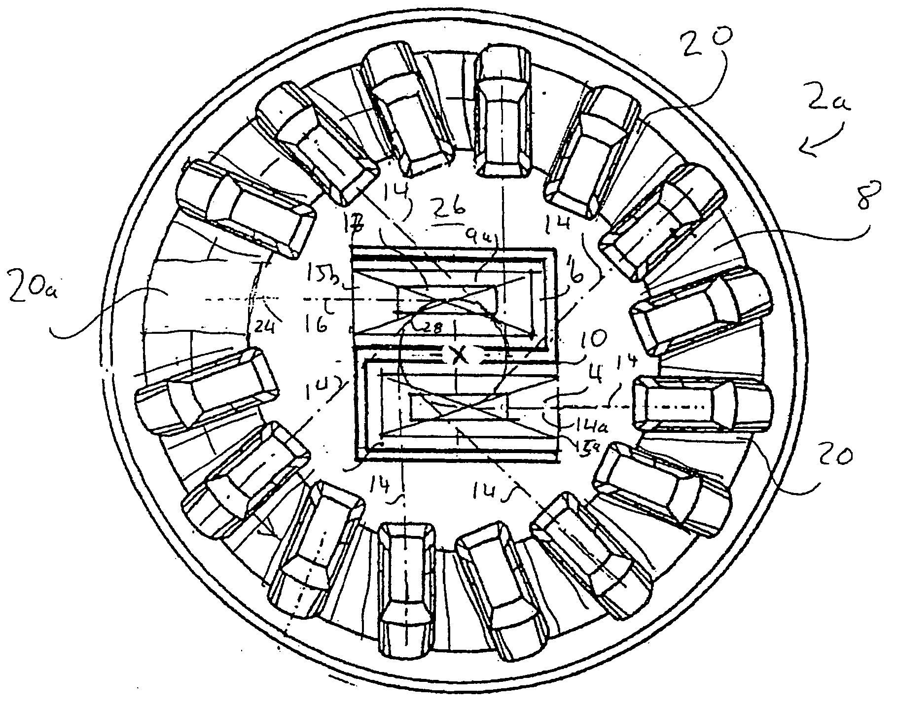
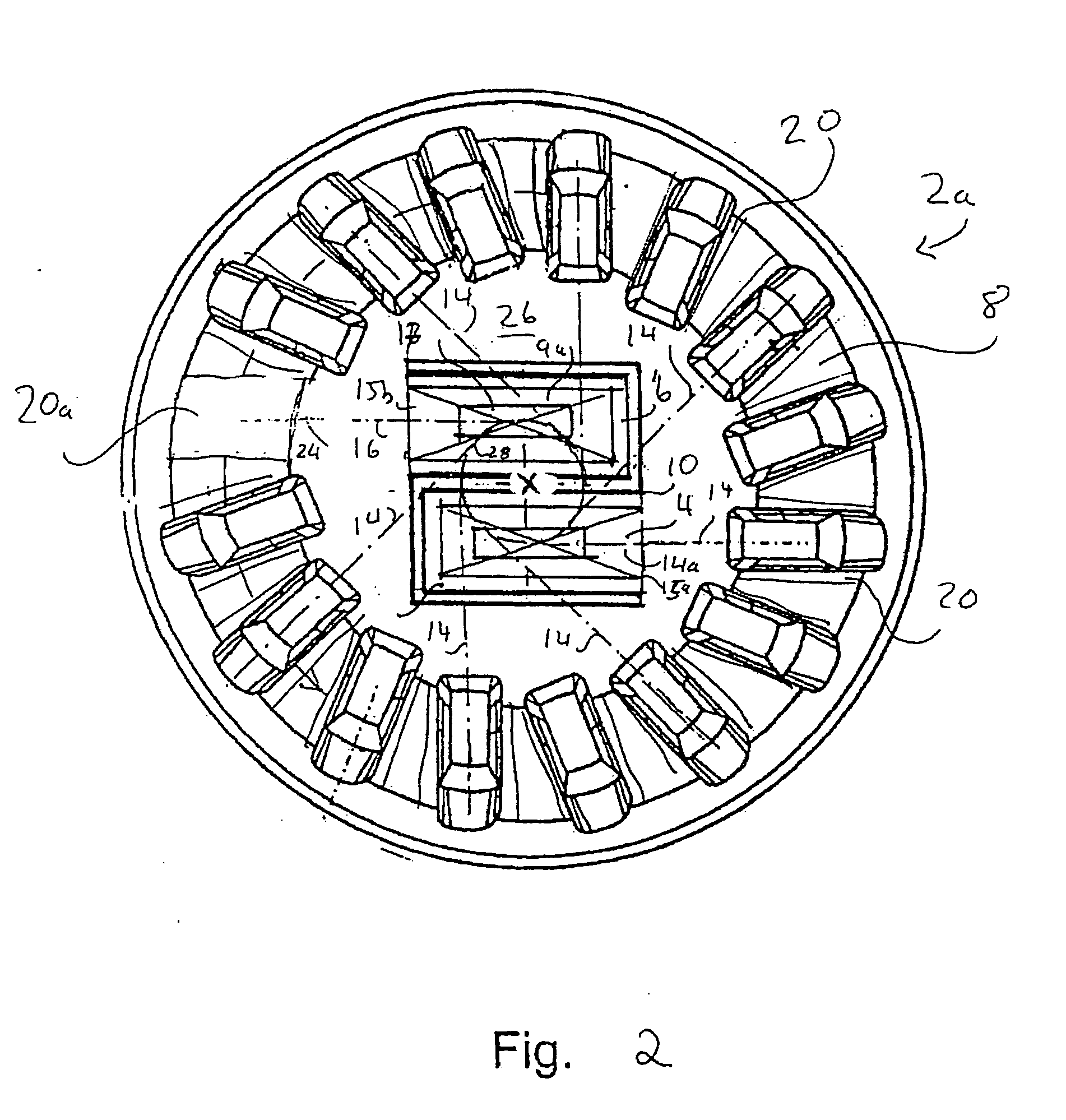
[0062]FIG. 2 shows one embodiment of the parking level 2, generally indicated by 2a. The parking level 2a includes an annular platform 8 rotatable about the central axis X of the installation. Two elevator shafts 4 and 6 are centrally located in an interior central space 26 of the parking level 2a. The elevators 4 and 6 share a common wall 10 that lies on a diameter of the parking level 2a. The elevators 4 and 6 have parallel base centerlines 14a and 14b, respectively, which are off-radial, i.e. neither of which lie on a diameter of the parking level 2a. The elevator shafts 4 and 6 each have an opening 15a and 15b, respectively, at the parking level 2a, facing opposite directions. The annular rotatable platform 8 comprises a plurality of parking spaces 20, having off-radially aligned center base lines, represented by broken lines 14.

[0063] Transferring a vehicle from an elevator car, for example, the elevator car 9a located in the elevator shaft 6, to a vacant parking space 20a tak...

second embodiment

[0066] Further attention is now directed to FIG. 3, illustrating a second embodiment of a parking level 2, generally indicated by 2b, that is part of the parking installation 1. The parking level 2b comprises an inner annular parking platform 54, and a rotatable outer parking platform 56. The parking platforms 54 and 56 are both coaxial with the axis X of the installation 1. The inner platform 54 has a sufficiently large inner diameter to surround a central region 59 including four elevator shafts 64a-64d, each servicing all levels of the installation 1.

[0067] The central region 59 is divided into four quadrants A, B, C and D by a cruciform partition wall 70.

[0068] In each one of the elevators 64a-64d, is an elevator car 9 upon which an electrically-powered motorized dolly 76 is installed. The motorized dolly 76 is loadable by a vehicle to be parked and functions in the same manner previously described, to transfer a vehicle from an elevator car 9 to a vacant parking space 80 that...

third embodiment

[0078]FIG. 5 illustrates another embodiment of a parking level 2, generally indicated by 2c. In this embodiment, the installation 1 comprises two elevators 156a and 156b located within a rotatable central circular region 160 in the interior of an annular stationary platform 162. The elevators 156a and 156b share a common wall 164 that lies on a diameter of the parking level 2c. The elevators 156a and 156b have parallel center base lines 166a and 166b respectively that face in opposite directions that are not radially aligned. The platform 162 comprises a plurality of non-radially aligned parking spaces 166, represented by dashed lines 166. The difference between the present embodiment and that illustrated in FIG. 1 resides in that the platform 162 is stationary and is served by the rotary bank of elevators 156a and 156b.

[0079] The bank of elevators rotates, until they are aligned with a parking space. Although the elevators turn together, they travel vertically quite independently ...


PUM


Abstract

A multi-level, automated vehicle parking structure comprising a plurality of horizontal, planar platform assemblies respectively located on a plurality of structure levels through which a central air shaft extends vertically. Each assembly comprises a rotary platform surrounding the shaft that is rotatable about a vertical axis of rotation extending through the shaft. In one embodiment, at least two oppositely directed vehicle elevators vertically and separately displaceable in the shaft have respective, substantially parallel, base centre lines that are off-radial with respect to the axis of rotation. Each rotary platform has a plurality of parking spaces arranged in circular array with respect to the axis of rotation and having respective base centre lines off-radially inclined in the same sense with respect to the axis of rotation Each rotatable platform is rotatably displaceable so as to bring any selected pair of opposite parking spaces into respective communication with the elevators with the central base lines of the elevators being co-directional with the central base lines of the selected parking spaces. The structure further comprises at least one vehicle entry and exit level for selective communication with the elevators for transfer thereto and therefrom of vehicles to be parked and to be retrieved. Motorised dollies transport vehicles between the elevators and the parking spaces on the stationary platform.

Description

RELATED APPLICATION [0001] This is a continuation-in-part of co-pending parent application PCT / IL01 / 00658 in which the U.S. has been designated, filed 18 Jul. 2001, the contents of which are hereby incorporated by reference, itself claiming priority from U.S. application Ser. No. 09 / 620,228, filed 20 Jul. 2000.FIELD OF THE INVENTION [0002] This invention relates, in general, to a multi-level, automated parking structure wherein entering vehicles can be automatically transferred by one or more elevators to levels of generally circular, particularly annular construction having vacant parking spaces and wherein means are provide for transferring vehicles from the elevators to the vacant parking spaces and, in reverse, for transferring the vehicles from the parking spaces to the elevators for subsequent retrieval. BACKGROUND OF THE INVENTION [0003] Automated parking systems are known which are provided with computerized and mechanical means to take control over a vehicle upon its arriva...

Claims


Application Information

Patent Timeline
Patent Type & Authority Applications(United States)
IPC IPC(8): E04H6/24E04H6/28
CPCE04H6/282E04H6/245
Inventor SEGAL, MAURICEWEISS, MENACHEM P.
Owner SEGAL
Why Eureka
Try Eureka