Method and apparatus for providing user specific downlink beamforming in a fixed beam network

a fixed beam network and beamforming technology, applied in the field of communication systems, can solve the problems of high angular spread, less effective beamforming, and poor user specific beamforming strategies for systems employing a very small number of closely spaced antennas

Active Publication Date: 2005-05-05
ALCATEL-LUCENT USA INC
View PDF23 Cites 25 Cited by
  • Summary
  • Abstract
  • Description
  • Claims
  • Application Information

AI Technical Summary

Problems solved by technology

However, user specific beamforming strategies that are appropriate for systems that employ a very small number of closely spaced antennas may not work well when extended to systems that have many closely spaced antennas.
The problem of high angular spread arises when there are a large number of spatially dispersed local scatterers around the mobile user.
Beamforming becomes less effective when angular spread is high because the signal energy arrives only partially co-phased at the mobile antenna.
Further, the fact that the P-CPICH phase-reference is not beamformed leads to much steeper degradation in performance because the pilot and traffic see different channels as angular spread increases.
These common beams are called fixed because they do not adapt to any particular user's location.
A steep decline in performance because of steep roll-off of the beam patterns

Method used


Image

  • Method and apparatus for providing user specific downlink beamforming in a fixed beam network
  • Method and apparatus for providing user specific downlink beamforming in a fixed beam network
  • Method and apparatus for providing user specific downlink beamforming in a fixed beam network

Examples


Embodiment Construction

[0024] One or more specific embodiments of the present invention will be described below. In an effort to provide a concise description of these embodiments, not all features of an actual implementation are described in the specification. It should be appreciated that in the development of any such actual implementation, as in any engineering or design project, numerous implementation-specific decisions must be made to achieve the developers' specific goals, such as compliance with system-related and business-related constraints, which may vary from one implementation to another. Moreover, it should be appreciated that such a development effort might be complex and time consuming, but would nevertheless be a routine undertaking of design, fabrication, and manufacture for those of ordinary skill having the benefit of this disclosure.

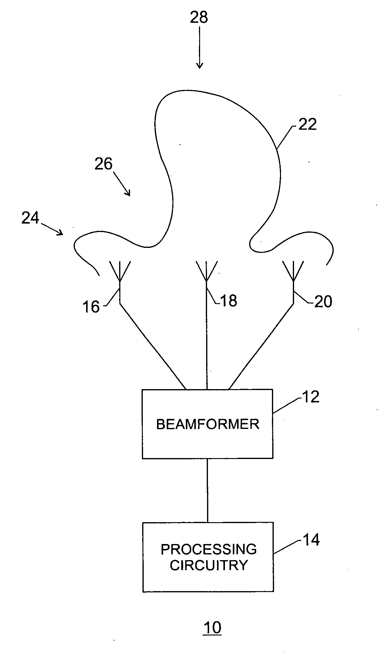
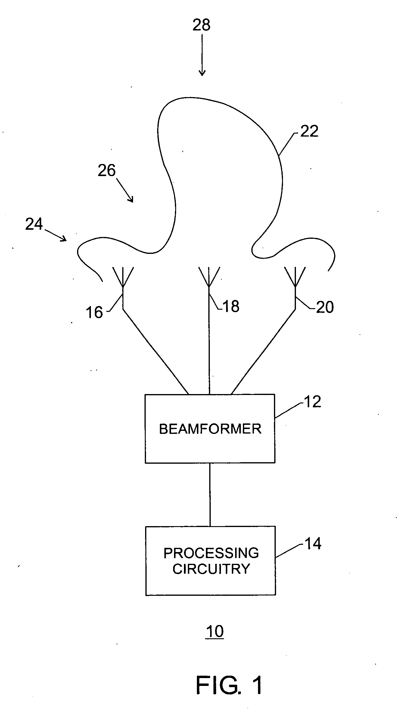
[0025] Embodiments of the present invention may form user-specific beams in the presence of a fixed beamforming network. If the network is configured to...


PUM


Abstract

The disclosed embodiments relate to a system and method for providing user specific beams in a fixed beam network, the fixed beam network comprising a plurality of fixed beams, each of the plurality of fixed beams being defined by a plurality of fixed beam correlation coefficients. The system may comprise a device that computes reception correlation data for a received signal, and a beamformer that is adapted to determine transmission weighting coefficients to be applied to a return signal based on the difference between the reception correlation data and the fixed beam weighting coefficients associated with at least one of the plurality of fixed beams.

Description

BACKGROUND OF THE INVENTION [0001] 1. Field of the Invention [0002] The present invention relates generally to communication systems that transmit, receive and process communication signals and, more particularly, to providing user specific downlink beamforming in a fixed beam network. [0003] 2. Description of the Related Art [0004] This section is intended to introduce the reader to various aspects of art that may be related to various aspects of the present invention, which are described and / or claimed below. This discussion is believed to be helpful in providing the reader with background information to facilitate a better understanding of the various aspects of the present invention. Accordingly, it should be understood that these statements are to be read in this light, and not as admissions of prior art. [0005] Communication systems that transmit and receive communication signals continue to grow in importance. Such systems are used to provide television, radio, satellite comm...

Claims


Application Information

Patent Timeline
IPC IPC(8): H01Q1/24H01Q25/00H04W16/28
CPCH01Q1/246H04W16/28H01Q25/00
Inventor NAGARAJ, SHIRISH
Owner ALCATEL-LUCENT USA INC
Why Eureka
Try Eureka