
Fluid aspiration device

a technology of aspiration device and fluid, which is applied in the field of fluid aspiration, can solve the problems of more strict regulation, more costly and more problematic, and correspondingly more expensive in the direction of diagnostics, diagnostic recording/measuring,

Inactive Publication Date: 2005-05-05
BREG
View PDF3 Cites 69 Cited by
  • Summary
  • Abstract
  • Description
  • Claims
  • Application Information

AI Technical Summary

Benefits of technology

[0012] The sampling valve is positioned in the sampling fluid passageway and has an open sampling position and a closed non-sampling position. The sampling valve prevents fluid communication between the disposal reservoir and the sampling outlet in the closed non-sampling position and enables fluid communication between the disposal reservoir and the sampling outlet in the open sampling position.
[0017] In accordance with a specific embodiment of the present aspiration method, the provided a fluid aspiration device further includes a sampling outlet, a sampling fluid passageway, and a sampling valve. The sampling fluid passageway is between the disposal reservoir and the sampling outlet. The sampling valve is positioned in the sampling fluid passageway. The sampling valve has an open sampling position and a closed non-sampling position. The sampling valve prevents fluid communication between the disposal reservoir and the sampling outlet in the closed non-sampling position and enables fluid communication between the disposal reservoir and the sampling outlet in the open sampling position.

Problems solved by technology

With the existence and increased awareness of many blood-borne pathogens, the handling, sampling and disposal of medical waste, such as aspirated bodily fluids, has become more strictly regulated and correspondingly more costly and more problematic.

Method used


Image

  • Fluid aspiration device
  • Fluid aspiration device
  • Fluid aspiration device

Examples


Embodiment Construction

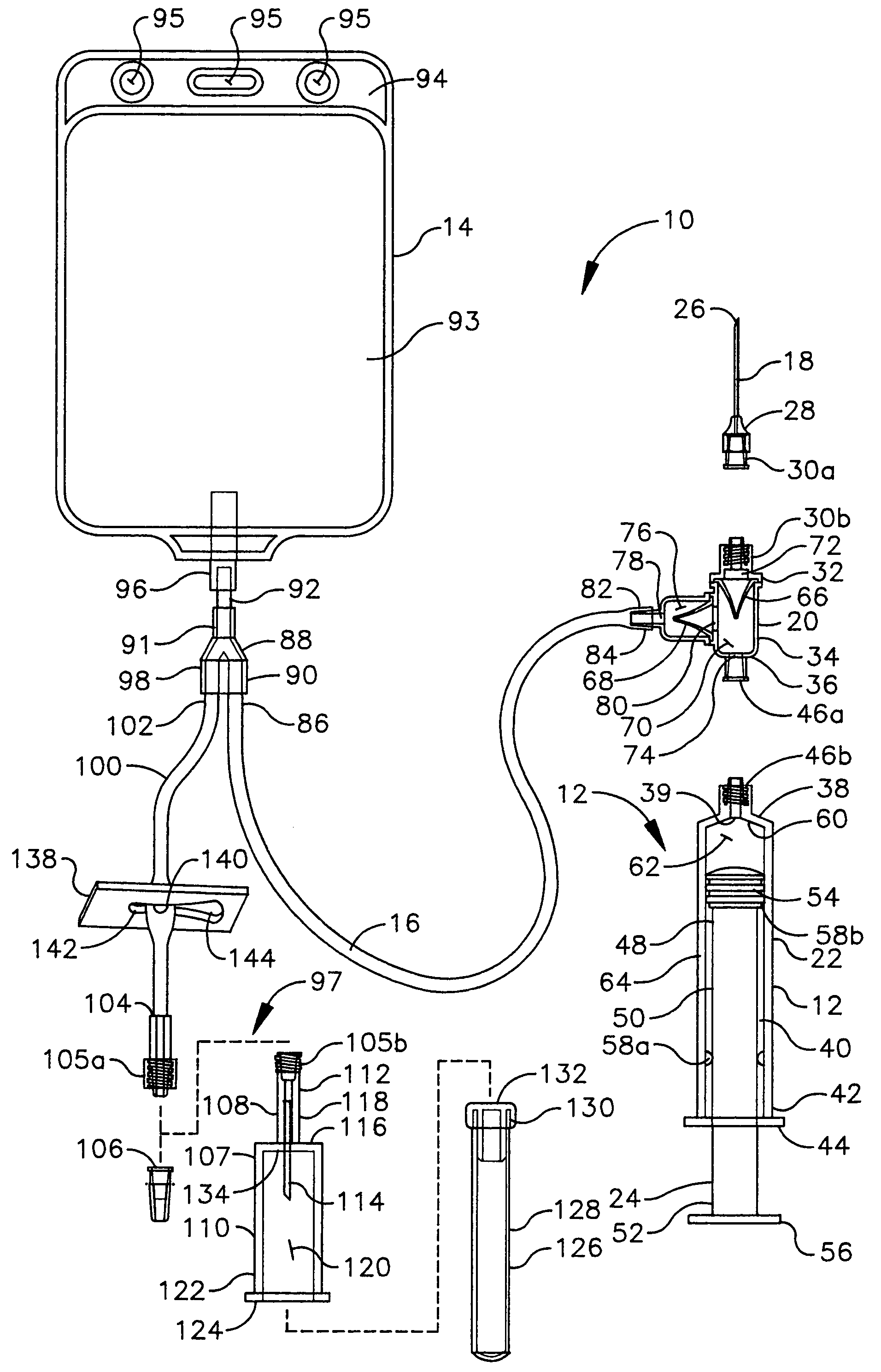
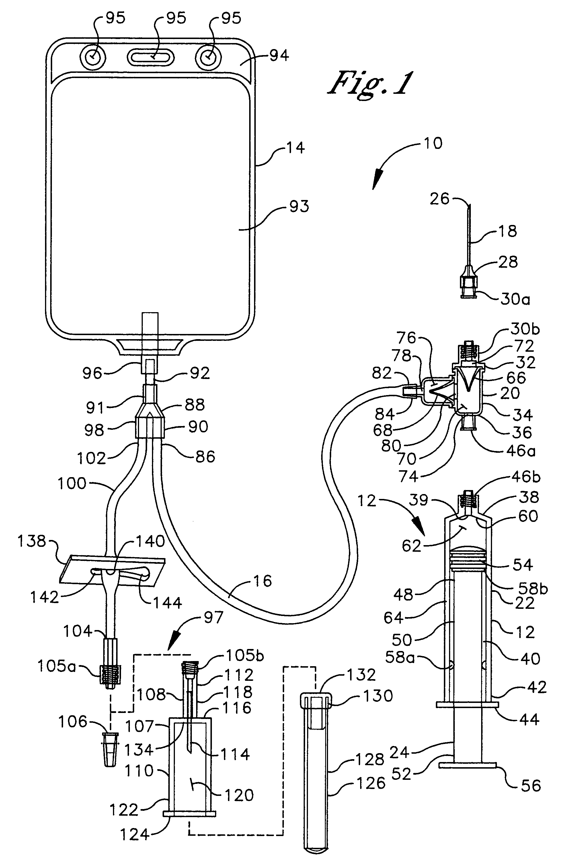
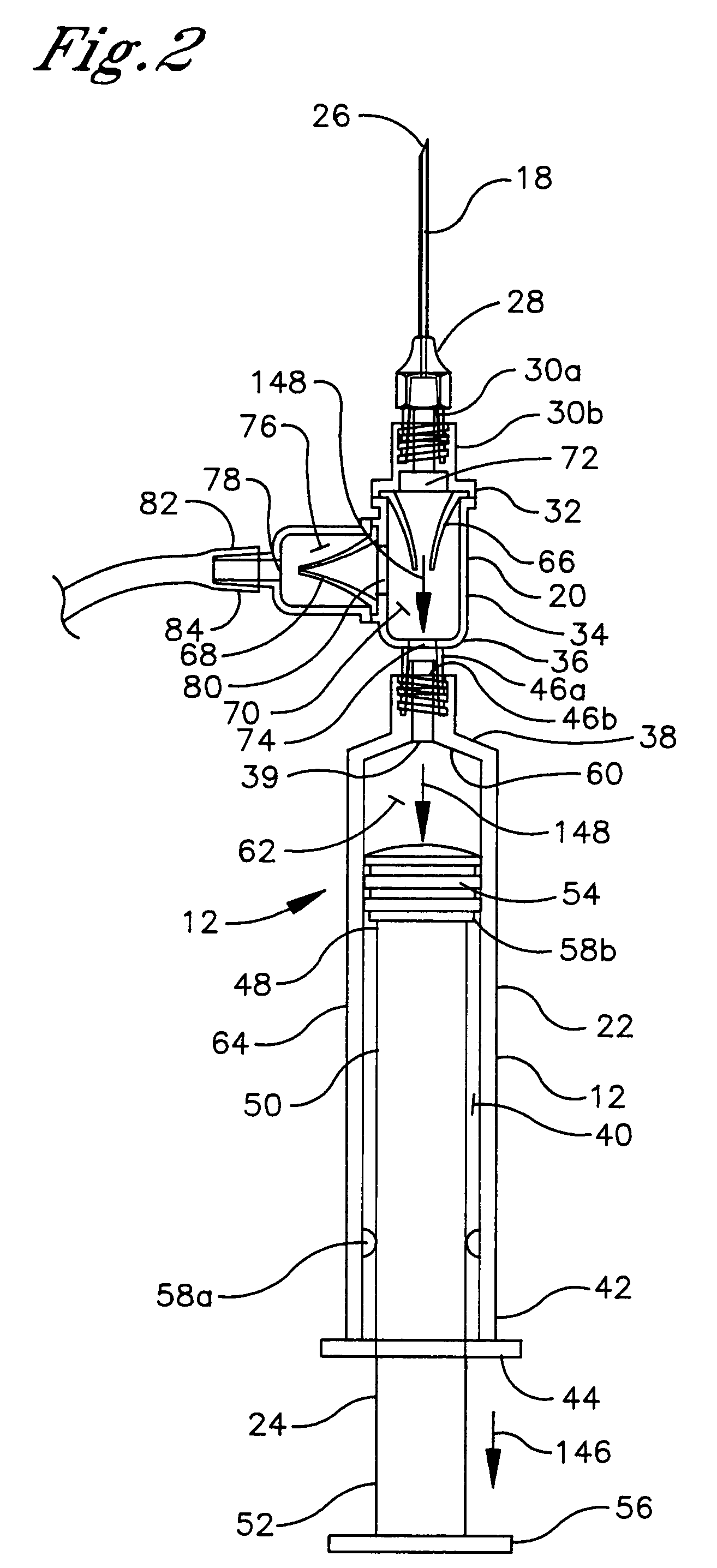
[0023] Referring to FIG. 1, an embodiment of a fluid aspiration device of the present invention is shown and generally designated 10. The fluid aspiration device 10 comprises a syringe 12, a disposal reservoir 14 and a disposal line 16 providing selective fluid communication between the syringe 12 and the disposal reservoir 14 in a manner described hereafter. The syringe 12 includes an aspiration intake 18, a valve assembly 20, a barrel 22 and a plunger 24, wherein the valve assembly 20 is positioned in series between the aspiration intake 18 and the barrel 22.

[0024] The aspiration intake 18 is preferably a conventional hollow syringe needle fabricated from a rigid metal and having an open front end 26, an open back end 28, and a continuous fluid passageway (not shown) extending therethrough. The front end 26 is a sharpened tip and the back end 28 is fixably attached in a fluid-tight manner to an aspiration intake coupler 30a, such as a releasable plastic male Luer lock fitting sho...


PUM


Abstract

A fluid aspiration device is provided having a syringe, a disposal reservoir and a disposal fluid passageway. The syringe has a variable-volume fluid chamber and an aspiration fluid passageway between the fluid chamber and a region of the body containing a fluid for aspiration. An aspiration valve is positioned in the aspiration fluid passageway. The disposal fluid passageway is between the fluid chamber and disposal reservoir and has a disposal valve positioned therein. The fluid is aspirated by expanding the variable volume of the fluid chamber to draw the fluid through the open aspiration valve into the fluid chamber. The aspiration valve is closed and the variable volume of the fluid chamber is contracted to open the disposal valve and displace the fluid into the disposal reservoir. When aspiration is terminated, the fluid aspiration device is maintained intact and the intact device including the fluid is disposed.

Description

TECHNICAL FIELD [0001] The present invention relates generally to fluid aspiration, and more particularly to a device for aspiration of fluid from the body, sanitary disposal of the fluid, and optional collection of a fluid sample. BACKGROUND OF THE INVENTION [0002] Localized accumulation of excess bodily fluid in an internal region of the body frequently occurs as a result of injury, infection, surgical trauma, or some other type of damage or disorder in that internal region of the body. It is generally desirable from a medical treatment standpoint to remove such excess accumulated bodily fluid from the body to reduce swelling and pain and to promote healing. Aspiration is a procedure for removing excess accumulated bodily fluid, which employs suction to draw the bodily fluid from the body. Aspiration procedures are commonly performed on joints. Aspiration of a joint is more specifically termed arthrocentesis. A syringe is the instrument of choice for performing arthrocentesis due ...

Claims


Application Information

Patent Timeline
IPC IPC(8): A61M1/00A61M5/142A61M31/00A61M39/24
CPCA61M1/0019A61M1/0023A61M1/0068A61M5/14216A61M39/24A61M1/0066A61M1/69A61M1/81A61M1/80
Inventor HOWARD, MARK E.
Owner BREG
Learn More