
Method and system for diagnostics and prognostics of a mechanical system

a mechanical system and diagnostic method technology, applied in the field of system for monitoring the condition of a mechanical system, can solve the problems of statistically unreliable, current systems do not allow concurrent data collection and data processing, and use of vibration analysis is usually limited to narrow bandwidth spectrum and a single domain, so as to achieve robust and efficient diagnostic and trending methods

Inactive Publication Date: 2005-05-05
RSL ELECTRONICS
View PDF60 Cites 304 Cited by
  • Summary
  • Abstract
  • Description
  • Claims
  • Application Information

AI Technical Summary

Benefits of technology

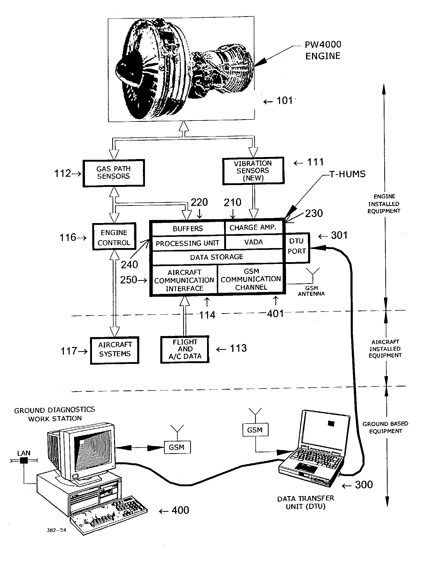
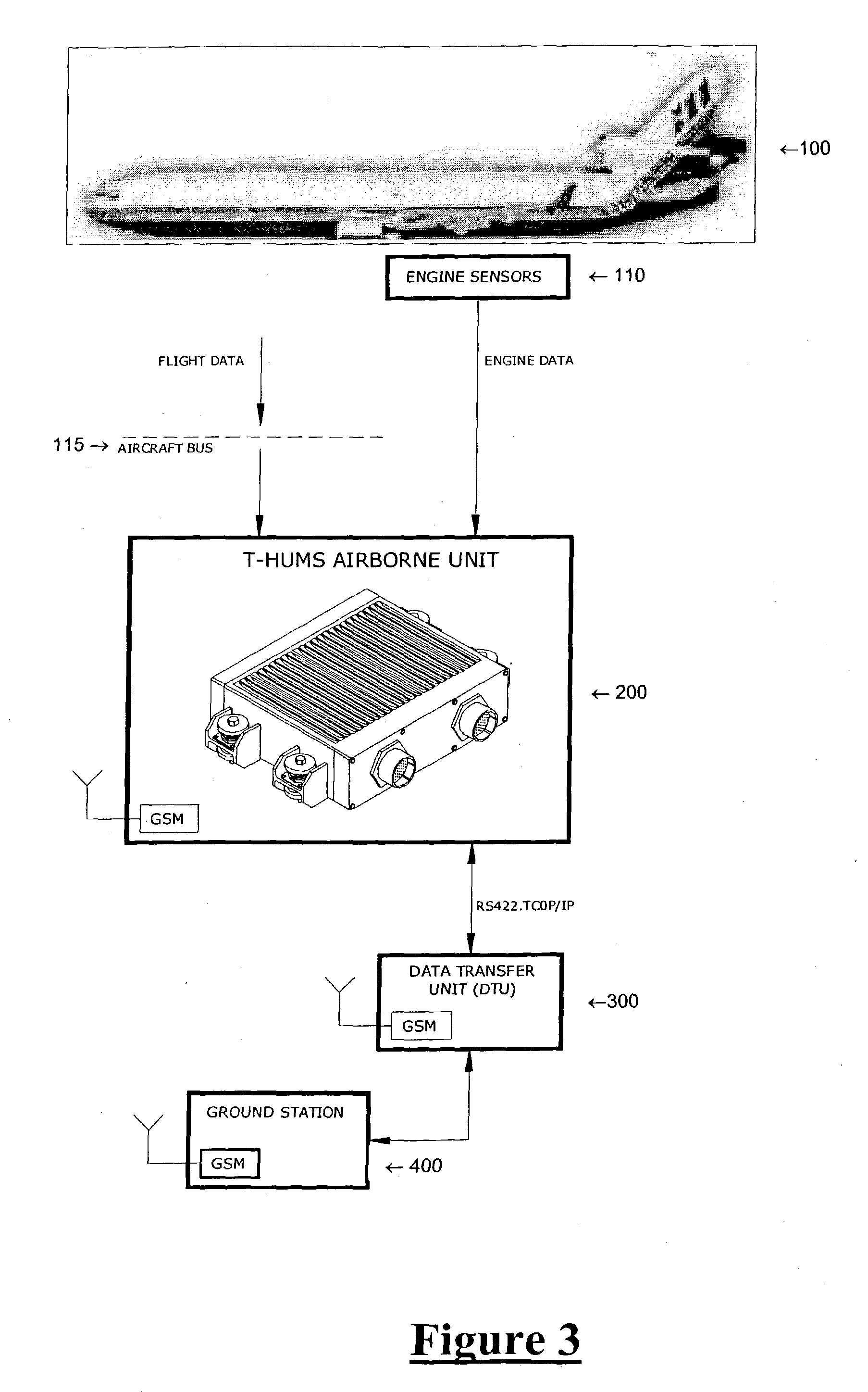
[0009] A robust and efficient diagnosing and trending method and system is provided for use in the maintenance of a mechanical system, such as an aircraft, or power plant. The invention is based on a multi-domain, wide-band analysis of the vibration patterns of various components of the mechanical system, which reflects the health of the corresponding components. The term Vib-RAY is used herein to refer to the multi-domain, wide-band vibration analysis of the present invention.
[0010] In accordance with the method of the present invention, sensors collect vibrational data. The vibration signatures of the monitored components are derived simultaneously in several domains: time, frequency, quefrency, time-frequency, order, amplitude, parameters, RPS-frequency (Rotations Per Second), and cycles. Because vibration signals in different domains, emphasize different faults, by correlating multiple signatures from various domains, the reliability of the diagnosis increases and the number of false alarms decreases.

Problems solved by technology

However, current systems do not allow for concurrent data collection and data processing.
Furthermore, the utilized vibration analysis is usually limited to narrow bandwidth spectrum and to a single domain, such as the frequency domain.
However, the FFT, because it is based on a single frame of data with a statistical error measured as 1 / (Number of frames), is statistically unreliable.
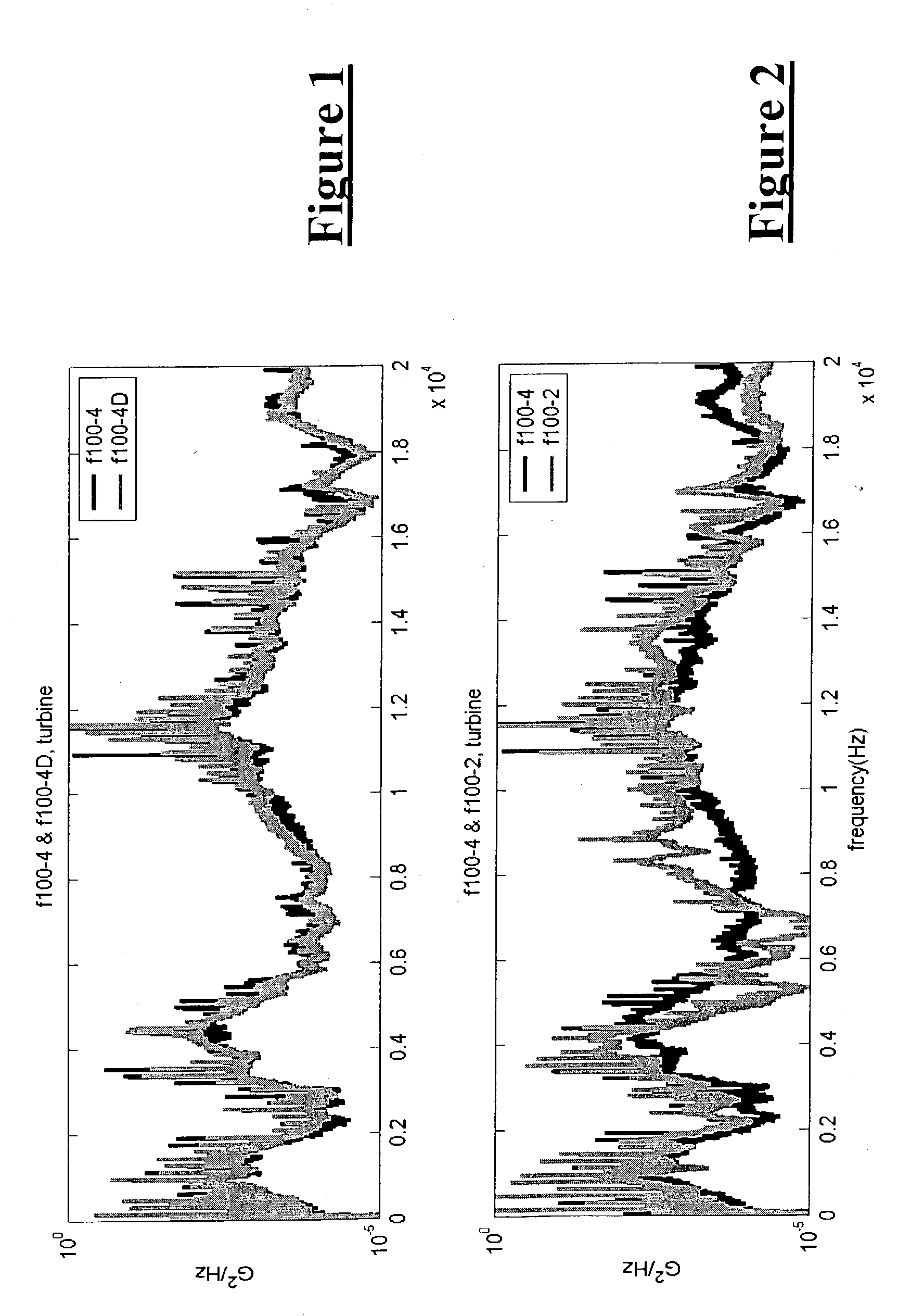
Even recent applications that have turned to the power spectral density (“PSD”) for vibration analysis, because it provides higher reliability than the FFT, are generally limited to a single domain.

Method used


Image

  • Method and system for diagnostics and prognostics of a mechanical system
  • Method and system for diagnostics and prognostics of a mechanical system
  • Method and system for diagnostics and prognostics of a mechanical system

Examples


Embodiment Construction

[0025] Although the following description refers to aircraft and engines, as may be appreciated, the subject invention is applicable to other type of machines, including helicopters, marine vehicles, land vehicles, electrical power generation stations, trains, engines, gear boxes, drive trains, rotors, generators, and pumps.

Analysis Domain Overview

[0026] The prior art vibrational signal analysis for monitoring the health of mechanical systems have largely been confined to analysis in the frequency domain. For example, both the FFT and the PSD spectrograms described above are in the frequency domain. This means the spectrograms depict a power or other value at different measured frequencies of the machine. However, other domains may be useful for health maintenance. These domains include time, order, quefrency, time-frequency response (“TFR”), amplitude, parameters, rotations-per-second (“RPS”) frequency, RPS-order, and cycles. Indeed, each of these domains has particular utility ...


PUM


Abstract

A vibrational analysis system diagnosis the health of a mechanical system by reference to vibration signature data from multiple domains. Features are extracted from signature data by reference to pointer locations. The features provide an indication of signature deviation from a baseline signature in the observed domain. Several features applicable to a desired fault are aggregated to provide an indication of the likelihood that the fault has manifested in the observed mechanical system. The system may also be used for trend analysis of the health of the mechanical system.

Description

FIELD OF THE INVENTION [0001] The present invention relates generally to a system for monitoring the condition of a mechanical system such as an aircraft engine. More specifically the invention relates to a diagnostic and prognostic method and system applicable to rotating machinery and in particular, aircraft engines and helicopter gearboxes. BACKGROUND OF THE INVENTION [0002] The use of vibration analysis as part of maintaining rotational mechanical systems is well known. Diagnostics of mechanical systems using vibration signatures have been researched in academic frameworks in connection with gear diagnostics, helicopter diagnostics, robots, ship vibrations, tool-ware monitoring, and transportation. Another application is power plant monitoring systems, especially those used in nuclear plants, which frequently use vibration signatures to identify worn parts requiring maintenance and other faults. [0003] In an aircraft engine, each machine (combination of parts applying energy to ...

Claims


Application Information

Patent Timeline
IPC IPC(8): G01H1/00G01M13/02G05BG06F11/30G06F15/00G21C17/00
CPCG01H1/006G05B23/0275G01M13/028
Inventor KLEIN, RENATA
Owner RSL ELECTRONICS
Learn More