
Storage device controlling device and control method for storage device controlling device

a storage device and control method technology, applied in the direction of instruments, input/output to record carriers, computing, etc., can solve the problems of inhibiting an increase in data access speed and taking more time to carry out data writing from the cpu, so as to reduce the idle time of the first processor (standby time for writing completion) and prolong the access time. , the effect of short access tim

Inactive Publication Date: 2005-05-05
GOOGLE LLC
View PDF3 Cites 19 Cited by
  • Summary
  • Abstract
  • Description
  • Claims
  • Application Information

AI Technical Summary

Benefits of technology

[0016] When the data transfer device controls the data transfer between the first memory and the second memory, the data transfer device needs to store the storage positions of data in the respective memories (the transfer source address and the transfer destination address for the data concerned) into a register. In the storage device controller of this invention, the data transfer information containing the information indicating the storage positions of the data is written in the third memory by the first processor. The data transfer device reads out the data transfer information from the third memory and stores it into the register. Therefore, the first processor writes the data transfer information, not into the register of the data transfer device, which requires a relatively long access time, but into the third memory, which requires only a relatively short access time, and then shifts to execution of the subsequent processing. Accordingly, the idle time of the first processor (standby time for writing completion) can be reduced, and the first processor can be efficiently operated. Therefore, the speed of the data reading / writing for the data input / output request from the information processing device can be increased.
[0017] As described above, the data reading / writing speed can be increased. The increase in data reading / writing speed greatly contributes to an increase in amount of data which is able to be handled in the information processing system and also to enhancement in the processing performance of the overall information processing system under a use condition of a recent storage system in which data input / output requests are successively transmitted from many information processing devices on-line and on a real-time basis.

Problems solved by technology

However, it takes more time to carry out data writing from the CPU into the register of the DMA controller in the data transfer circuit containing the DMA controller as compared with data writing from the CPU into a memory element.
Therefore, in a situation in which data transfer occurs frequently, the time needed for the DMA starting processing involving the data writing from the CPU into the register of the DMA controller inhibits an increase in the data access speed.

Method used


Image

  • Storage device controlling device and control method for storage device controlling device
  • Storage device controlling device and control method for storage device controlling device
  • Storage device controlling device and control method for storage device controlling device

Examples


first embodiment

(First Embodiment)

[Overall Construction]

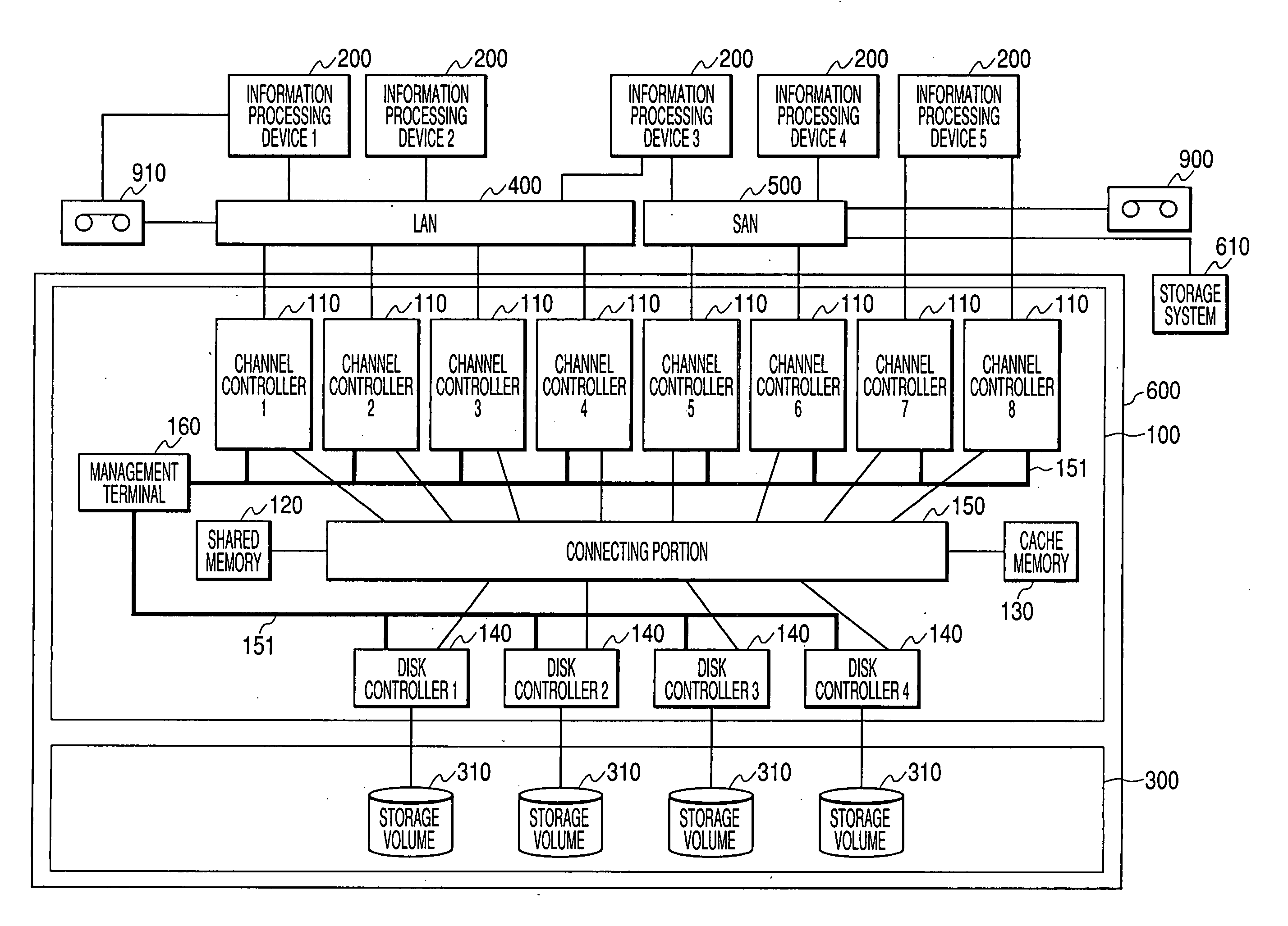
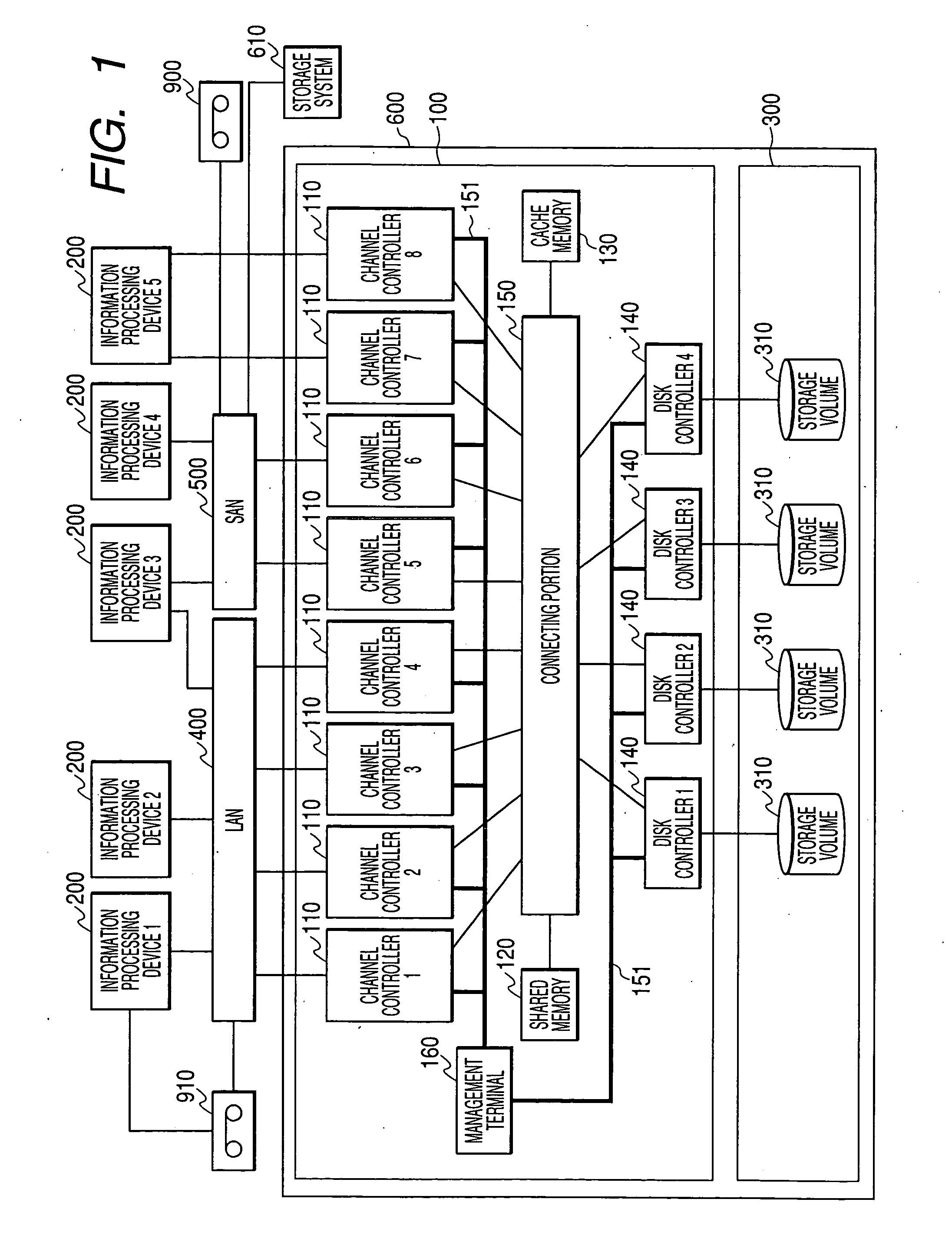
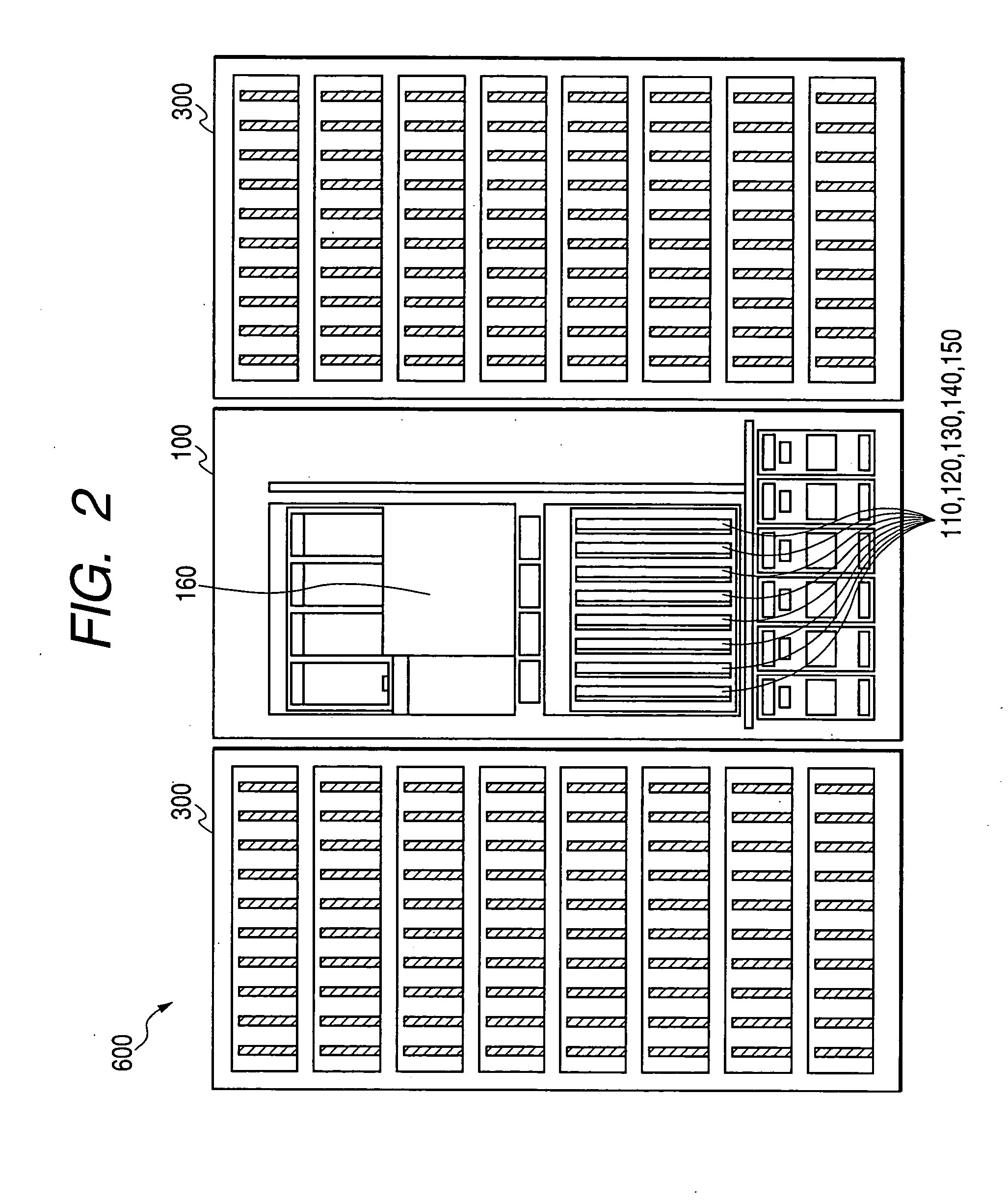
[0048] First, the overall construction of a storage system 600 containing a storage device controller 100 according to an embodiment of the present invention will be described with reference to the block diagram of FIG. 1.

[0049] The storage system 600 is equipped with a storage device controller 100 and a disk drive device 300. The storage device controller 100 controls the disk drive device 300 according to a command received from an information processing device 200. For example, the storage system 600 receives a data input / output request from the information processing device 200, and it reads / writes data stored in a storage volume 310 equipped to the disk drive device 300. The storage volume 310 is defined as a storage resource for storing data, which contains a physical volume serving as a physical storage area supplied by a disk drive, such as a hard disk device or the like, and a logical volume serving as a storage area set logically ...

second embodiment

(Second Embodiment)

[0226] The first embodiment may be modified like the second embodiment shown in FIGS. 25 to 27. In the second embodiment, the data transfer is carried out without using the script for the processor 2 in the first embodiment.

[0227] In this case, the transfer data is stored in the memory 2 (113), but the script for the processor 2 is not stored in the memory 1 (113) as shown in FIG. 25. In place of that, the area head address of the memory 2 (113) is stored in the script for the processor 1 of the memory 1 (117) as shown in FIG. 26.

[0228] The processing flow of the data transfer carried out between the memory 2 (113) and the cache memory 130 according to the second embodiment will be described with reference to the flowchart of FIG. 27.

[0229] The processor 2 (112) secures the data area (S6000). The securement of the data area means that when the file access request transmitted from the information processing device 200 is a read-out request, a storage area for st...

third embodiment

(Third Embodiment)

[0243] Furthermore, a third embodiment shown in FIG. 28 may be implemented. That is, in the third embodiment, the same DMA transfer as the first embodiment or the second embodiment is implemented in the information processing device 200, such as a computer or the like, which is connected to a network, such as LAN 400 or the like.

[0244] The information processing device 200 is equipped with a processor 1 (first processor) 209, a processor 2 (second processor) 202, DMA (data transfer device) 204, a memory 1 (third memory) 207, a memory 2 (second memory) 203, a memory controller 1 (201), a memory controller 2 (201), an I / O controller 205 and a storage device (first memory) 210.

[0245] The processor 2 (202), the memory 2 (203) and the memory controller 2 (201) provides a communication interface function for carrying out communications with other information processing devices 200 through LAN 400. For example, the communication interface function will enable reception ...


PUM


Abstract

A storage device controller has a channel controller a disk controller; and a first memory for storing data delivered between the channel controller and the disk controller. The channel controller has a circuit board on which a first processor, a file access processor having a second processor and a second memory, a data transfer device and a third memory are formed. The second processor transmits information indicating the storage position of data in the second memory to the first processor, the first processor writes into the third memory data transfer information containing information indicating the storage position of data in the first memory and information indicating the storage position of the data in second memory, and the data transfer device reads out data transfer information from the third memory and controls the data transfer between the first memory and the second memory on the basis of data transfer information thus read out.

Description

CROSS-REFERENCES TO RELATED APPLICATIONS [0001] This application relates to and claims priority from Japanese Patent Application No. 2003-368591, filed on Oct. 29, 2003, the entire disclosure of which is incorporated herein by reference. BACKGROUND OF THE INVENTION [0002] The present invention relates to a storage device controller, and a method of controlling the storage device controller. [0003] The amount of data to be handled in a computer system has recently increased. In connection with this increase in the data amount, a large-scale storage system equipped with a storage volume which is managed by a RAID (Redundant Arrays of Inexpensive Disks) system for supplying enormous storage resources, referred to as a mid-range class or enterprise class, has recently received widespread attention as a storage system for managing large amounts of data. Furthermore, a technique in which information processing devices are connected to a storage system through a dedicated network (Storage ...

Claims


Application Information

Patent Timeline
Patent Type & Authority Applications(United States)
IPC IPC(8): G06F13/28G06F3/06G06F12/00G06F13/38
CPCG06F3/0613G06F3/0656G06F13/385G06F3/067G06F3/0659
Inventor KANAI, HIROKI
Owner GOOGLE LLC
Learn More