
Method of fault correction for an array of fusible links

a fault correction and array technology, applied in error detection/correction, instruments, computing, etc., can solve problems such as erroneous data representation by faulty fusible links, and achieve the effect of improving the robustness of arrays of fusible links

Inactive Publication Date: 2005-05-05
LEXMARK INT INC
View PDF42 Cites 6 Cited by
  • Summary
  • Abstract
  • Description
  • Claims
  • Application Information

AI Technical Summary

Benefits of technology

[0010] An advantage of the present invention is improved robustness of an array of fusible links, such as for example, the fusible links present on an ink jet printhead.
[0011] Another advantage of the invention is that a determination of an opened, i.e., blown, fusible link may be made even though the resistance of the fusible link is not infinity, and may, for example, be between 1 k ohms and 30 k ohms.

Problems solved by technology

In other words, since the fusible link is not vented to the atmosphere, the particles making up the fusible link are still present after the fusible link is blown, and under certain electrical and / or mechanical conditions, e.g., voltage and / or vibration, the gap in the fusible link may be bridged, thereby returning from a blown (opened) state to a non-blown state, which in turn leads to an erroneous representation of data by the faulty fusible link.

Method used


Image

  • Method of fault correction for an array of fusible links
  • Method of fault correction for an array of fusible links
  • Method of fault correction for an array of fusible links

Examples


Embodiment Construction

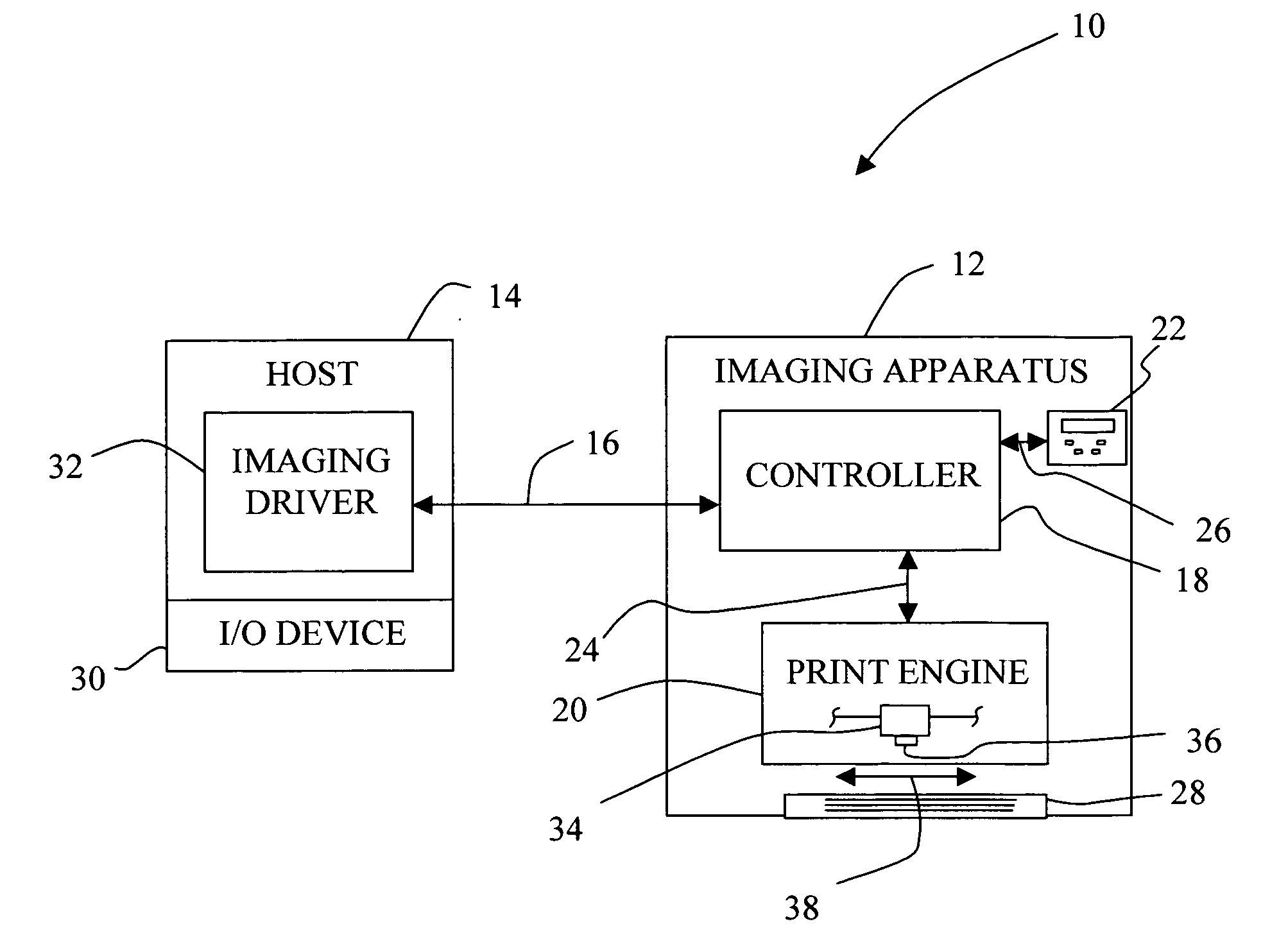
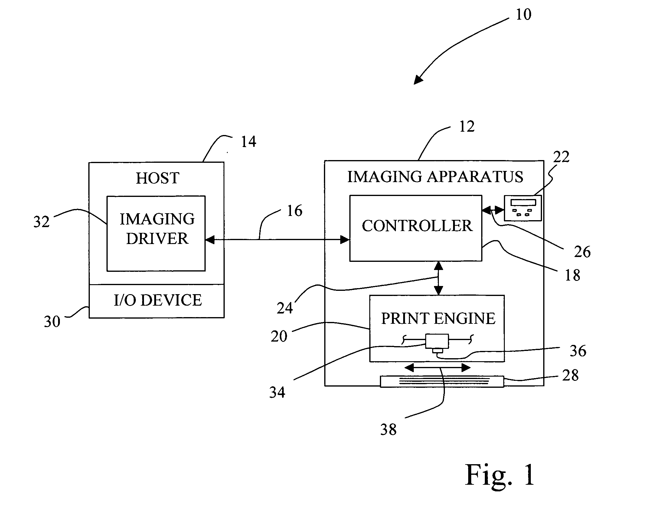
[0021] Referring now to the drawings, and particularly to FIG. 1, there is shown a diagrammatic depiction of a system 10 embodying the present invention. System 10 includes an imaging apparatus 12 and a host 14. Imaging apparatus 12 communicates with host 14 via a communications link 16.

[0022] Imaging apparatus 12 can be, for example, an ink jet printer and / or copier. Imaging apparatus 12 includes a controller 18, a print engine 20 and a user interface 22.

[0023] Controller 18 includes a processor unit and associated memory, and may be formed as an Application Specific Integrated Circuit (ASIC). Controller 18 communicates with print engine 20 via a communications link 24. Controller 18 communicates with user interface 22 via a communications link 26.

[0024] Host 14 may be, for example, a personal computer including an input / output (I / O) device 30, such as keyboard and display monitor. Host 14 further includes a processor, input / output (I / O) interfaces, memory, such as RAM, ROM, NVR...


PUM


Abstract

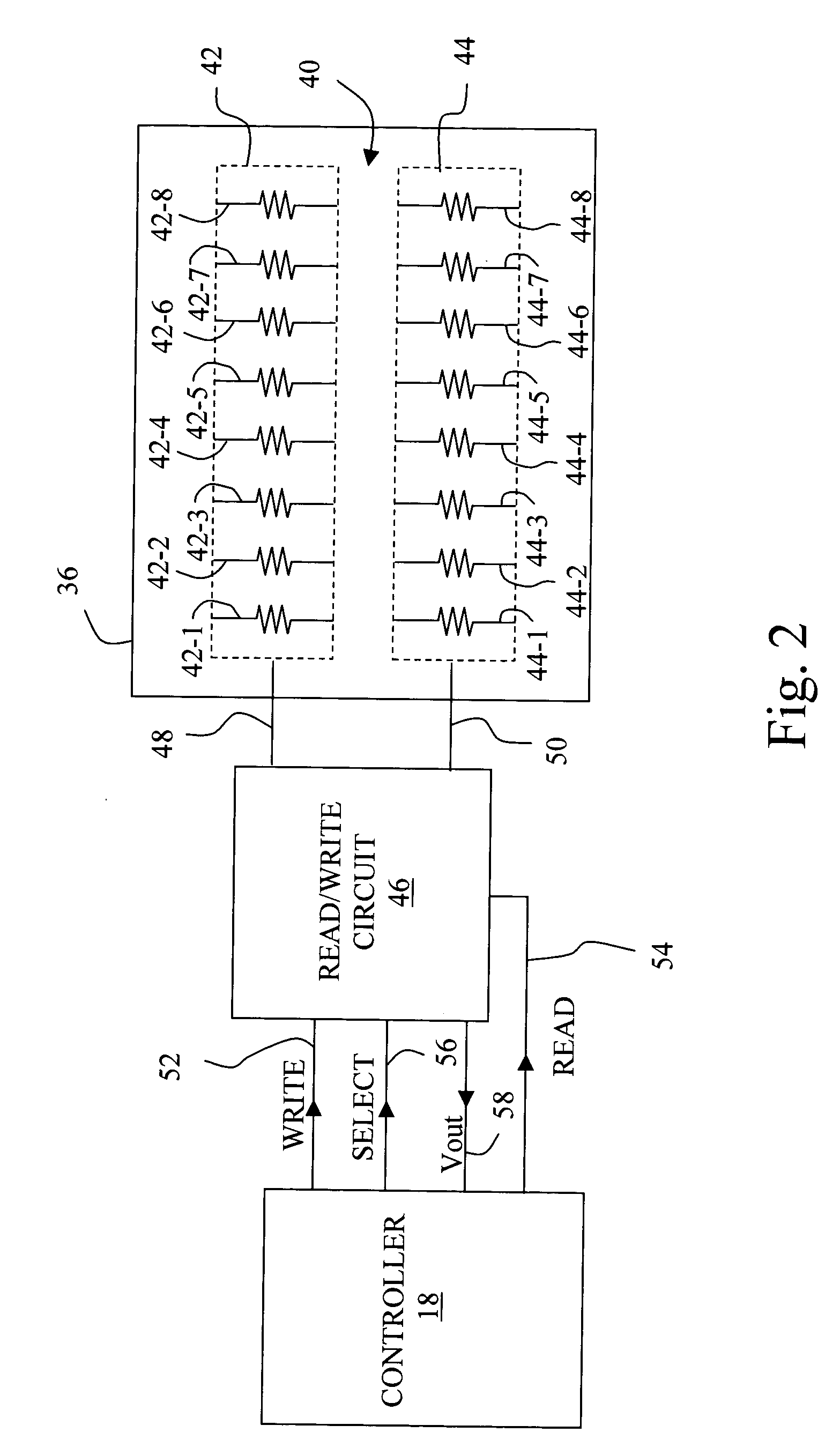
A method of fault correction for an array of fusible links includes the steps of storing digital information in a first plurality of fusible links to place the first plurality of fusible links in a first programmed state; storing the digital information in a second plurality of fusible links to place the second plurality of fusible links in a second programmed state; and performing a logic operation to combine the first programmed state with the second programmed state, the logic operation providing an output that is identical to one of the first programmed state and the second programmed state for a respective one of the first plurality of fusible links and the second plurality of fusible links that does not include a faulty bit.

Description

BACKGROUND OF THE INVENTION [0001] 1. Field of the Invention [0002] The present invention relates to improving the robustness of an array of fusible links, and, more particularly, to a method of fault correction for an array of fusible links. [0003] 2. Description of the Related Art [0004] In a printing environment, fusible links, also referred to as micro-fuses, are located on a printhead cartridge to store cartridge related information, such as for example, manufacturing information, ink capacity, ink type, cartridge type, cartridge identification number, etc. Such fusible links may be fabricated as a part of a silicon chip, and may be formed on the silicon chip commonly referred to as a printhead chip that includes such components as, for example, ink jetting heater elements. It has been discovered that due to the sealed nature of the silicon chip, a “blown”, i.e., opened, fusible link can potentially reattach itself under certain conditions. In other words, since the fusible lin...

Claims


Application Information

Patent Timeline
IPC IPC(8): G06F11/00
CPCB41J29/393
Inventor AHNE, ADAM JUDECROLEY, DONALD FREDEDELEN, JOHN GLENNROWE, KRISTI MAGGARDSTRUNK, TIMOTHY LOWELL
Owner LEXMARK INT INC
Learn More