
Electrostatic device for ionic air emission

a technology of ionic air emission and electrostatic filter, which is applied in the direction of external electric electrostatic seperator, electrostatic cleaning, particle charging/ionising station, etc., can solve the problems of reducing the efficacy of electrofilters, high cost and high efficacy, and double-stage electrofilters,

Inactive Publication Date: 2005-05-12
AIRINSPACE S E
View PDF27 Cites 10 Cited by
  • Summary
  • Abstract
  • Description
  • Claims
  • Application Information

AI Technical Summary

Benefits of technology

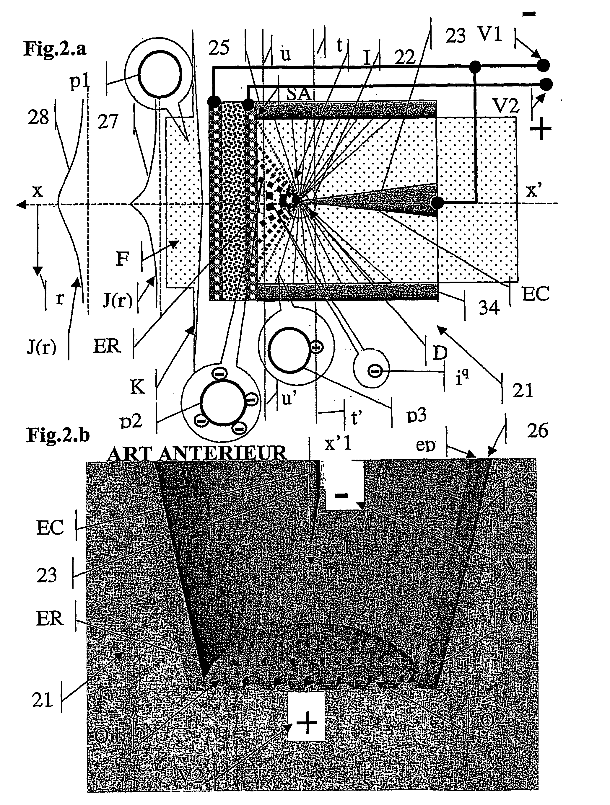
[0036] An electrostatic ionic emission device according to the present invention is of the type described hereinbelow constituted by the combination between—on the one hand, a conductive discharge corona electrode, subjected to an electric discharge potential and emitting a flow of ions,—and, on the other hand, a conductive non-corona receptor electrode, subjected to a different electric reception potential. The receptor electrode has a pseudo-planar active face, situated opposite the corona electrode and distant from its discharge zone. The free space separating the active face of the receptor electrode from the corona electrode is free. A multitude of through channels of fluid traverses the receptor electrode. They terminate via a multitude of quasi-circular orifices, on its active face, according to a so-called flow axis, substantially perpendicular to the active face. These channels ensure, in the vicinity of the active face, a flow of the fluid according to veins crossing the receptor electrode and are overall substantially parallel to the flow axis of fluid charged with aerosol particles. The device further comprises means for pressurising a fluid, ensuring movement of the fluid (especially across the thickness of the receptor electrode), substantially in said flow axis and along the veins. The device is equipped with a source of electric current, comprising at least two metallic terminals having a sufficiently high electric potential difference between them (of the order of 5000V) and at least two conductors, each connected by an end to one of the potential terminals and / or to earth, and by the other end, respectively to a difference of the corona electrodes and receptor, to subject these two electrodes to a difference in electric potential sufficient to ensure ionic emission in the discharge zone of the corona electrode.

Problems solved by technology

Double-stage electrofilters, also known as electrostatic precipitators, are highly complex, very costly and high efficacy.
A first major fault in ionisation systems according to the prior art is that they do not have any means allowing a uniform quantity of ions to be deposited on the treated aerosol particles.
This reduces the efficacy of the electrofilters.
A second limitation to the prior art relative to ionic treatment of particles is that it does not provide an arrangement for depositing, on aerosol particles, a quasi-homogeneous quantity of ions (iq+) and (iq−) of opposite charges.
This seems due to the fact that at first it seems undesirable (even harmful) to deposit opposite charges on the same aerosol particle.
These two first types of faults of the prior art are mainly due to the fact that the flow of treated air has a transverse section generally vastly superior to the efficacious transverse dimension of the discharge zones of corona electrodes used.
A third defect in the prior art is that when it aims to homogenise a flow of ions, this is done:—either in the event where there is no displacement of fluid (such as in xerographic systems),—or in the event of geometry not permitting homogeneous ionic charging of aerosol particles within substantial fluid rates.
This device does not permit and furthermore does not claim homogenisation of the deposit of ions on the aerosol particles.
This device does not allow and also does not claim homogenisation of the deposit of ions on the aerosol particles.
Apart from its orifices, the receptor electrode does not comprise any particular surface geometry suitable for enabling homogenisation of a flow of ions.

Method used


Image

  • Electrostatic device for ionic air emission
  • Electrostatic device for ionic air emission
  • Electrostatic device for ionic air emission

Examples


Embodiment Construction

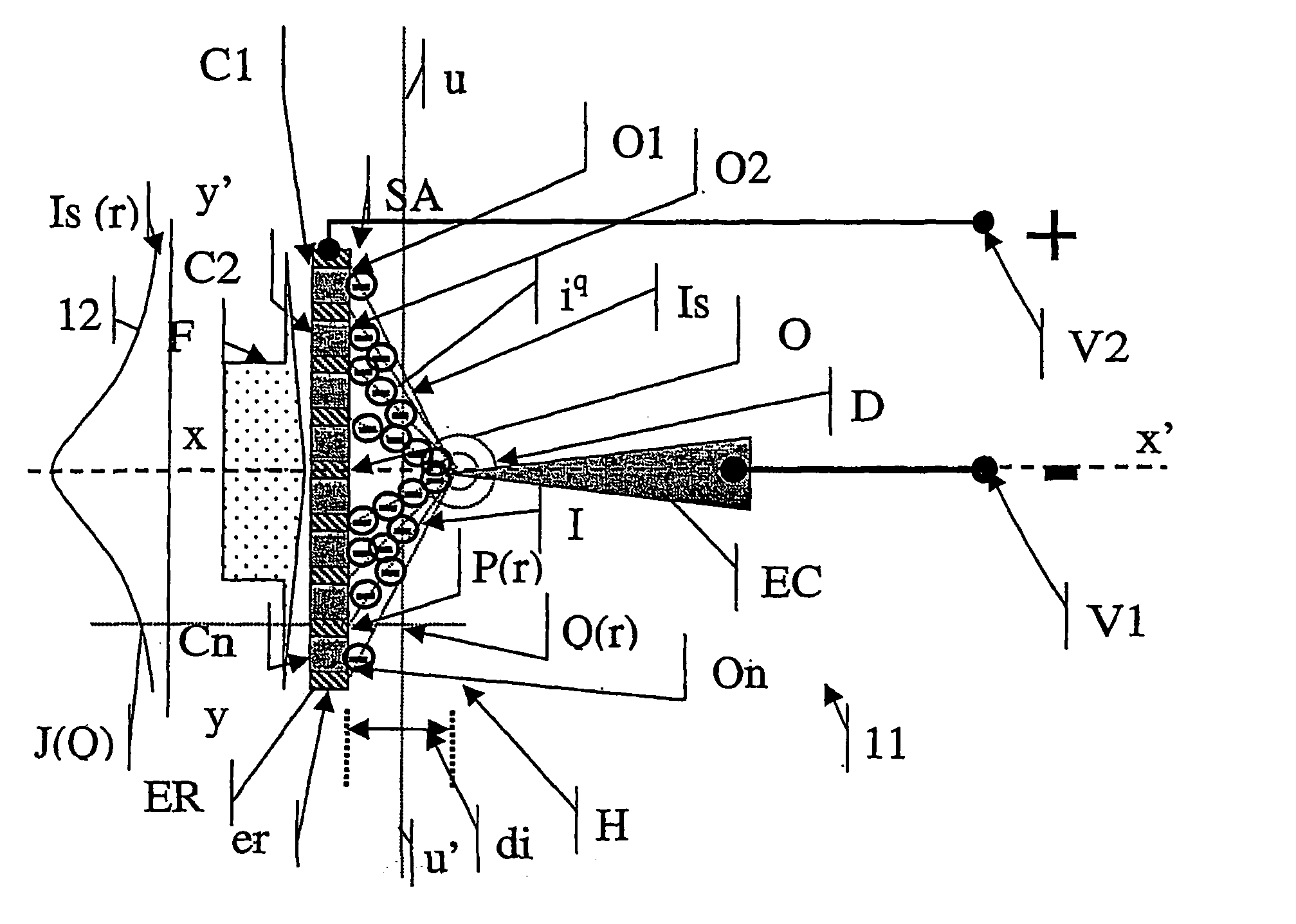
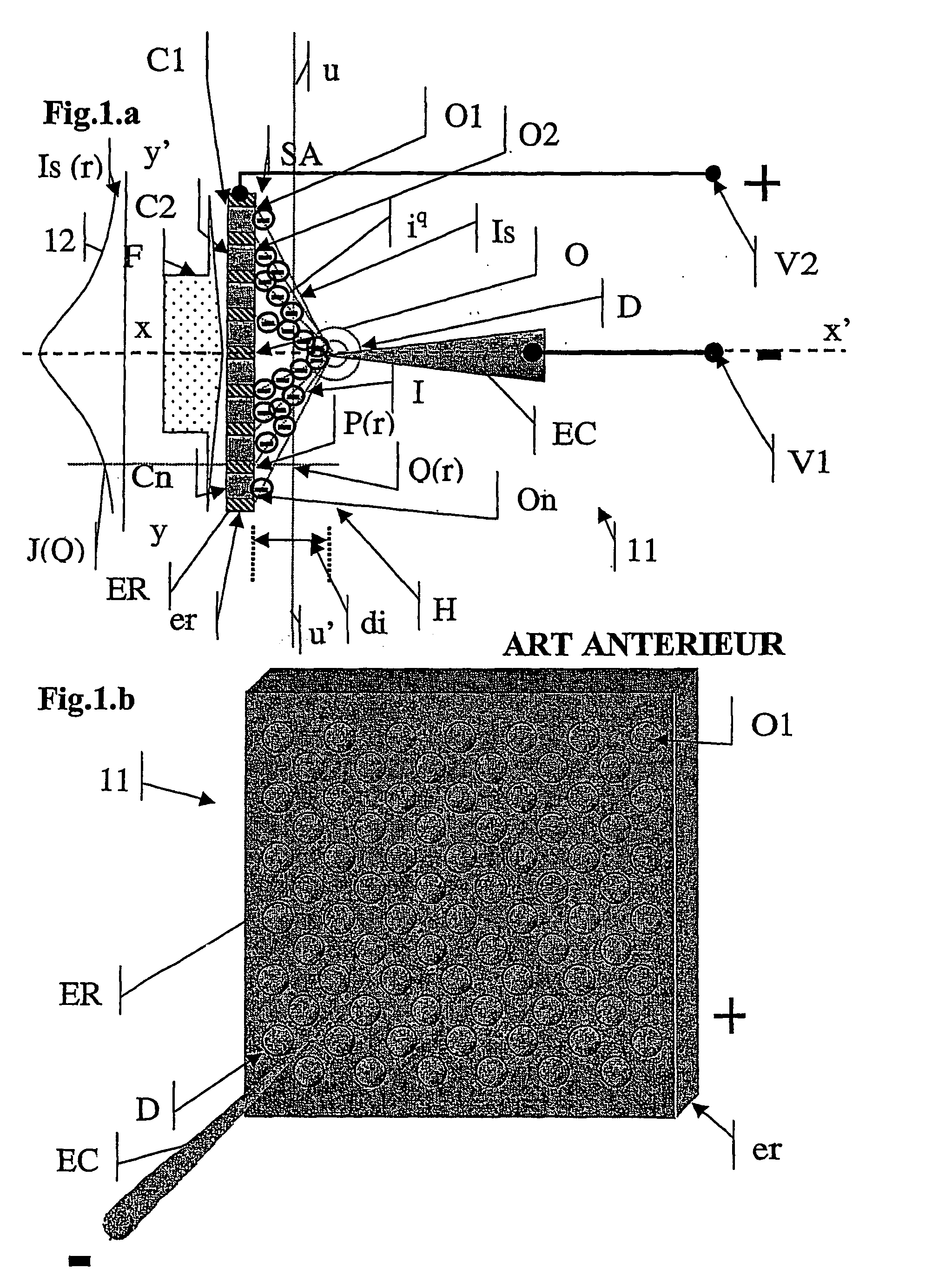
[0051]FIGS. 1.a and 1.b show diagrammatically, in section (FIG. 1.a) and in perspective (FIG. 1.b), an electrostatic ionic emission device (11) according to the prior art. The electrostatic ionic emission device (11) according to the prior art comprises a corona discharge conductive electrode (EC), subjected to a negative electric discharge potential (VI), emitting a global flow (I) of negative ions (iq). It also comprises a non-corona conductive receptor electrode (ER), subjected to a positive electric receptor potential (V2). The receptor electrode (ER) has an active face (SA) situated opposite the corona electrode (EC). It is at a distance (di) from its negative ion (iq) discharge zone (D). The space (H) separating the active face (SA) of the corona electrode (EC) is free. The receptor electrode (ER) is porous. It has a multitude of through channels of the fluid (C1, C2, . . . , Cn), traversing the receptor electrode (ER), and terminating in a multitude of orifices (O1, O2, . . ....


PUM


Abstract

The invention concerns an electrostatic ionic emission device (1) for depositing on the surface (sp) of a plurality of particles (p1, p2, pn) aerosols within a fluid (F), a quasi-homogeneous amount of ions (Iq). The device (1) comprises a discharge corona conductive electrode (EC), and a non-corona conductive receptor electrode (ER). The pseudo-planar active surface (SA) of its receptor electrode (ER) is covered with a quasi-uniformly distributed plurality of sharp-edged craters, enclosed by a pseudo-circle, having on their end edges (Ai) a section with minimum bend radius, and enclosing orifices (O1, O2, On), emerging outwards of the active surface (SA). Said sharp-edged craters are quasi-uniformly distributed on the active surface (SA), in both its geometrical directions. The surface flow of ions (Iq) derived from the corona electrode (EC) towards the active surface of the receptor electrode (ER) has increased homogeneity. Preferably, the receptor electrode (ER) is produced by means of an array (R′xyz) of metal fins.

Description

TECHNICAL FIELD OF THE INVENTION [0001] The present invention relates to the technical field of electrostatic air conditioning devices, and more specifically to devices for submitting a multitude of aerosol particles (such as dust, bio-aerosols or specific molecules, . . . ) within a moving fluid to the action of an ionic flow originating from corona discharge electrode, with a view: [0002] on the one hand to homogenising the flow of ions relative to the active plane face of a receptor electrode, [0003] and, on the other hand, to depositing on the surface of this multitude of aerosol particles (belonging to the same class of diameter) a quasi-homogeneous quantity of ions. [0004] The aim of this homogenisation of the deposit of ions on the surface of the particles can be to impart mechanical, physical, chemical, energetic consequences of reduced intensity. [0005] The invention relates to specifically to the technical field of electrostatic ionic emission and deposit devices of the ty...

Claims


Application Information

Patent Timeline
IPC IPC(8): B08B6/00B01J19/08B03C3/38B03C3/41B03C3/51B05B5/08
CPCB01J19/088B01J2219/0809B01J2219/0849B03C3/09B03C3/38B03C2201/10B03C3/47B03C3/51B03C3/60B03C2201/06B03C3/41Y02A50/2351
Inventor BILLIOTTE, JEAN-MARIENAGOLKIN, ALEXANDRE VLADIMIROVITCHBASSET, FREDERICVOLODINA, ELENA VLADIMIROVNA
Owner AIRINSPACE S E
Learn More