

Method and device for vacuum-coating a substrate
a technology of vacuum coating and substrate, which is applied in the direction of solid-state diffusion coating, superimposed coating process, manufacturing tools, etc., can solve the problems of inability to control individual layers, limited charge density and the ability to scale the method upward for industrial charge quantities, and inability to achieve individual layer deposition. , to achieve the effect of reducing friction and high ra
- Summary
- Abstract
- Description
- Claims
- Application Information
AI Technical Summary
Benefits of technology
Problems solved by technology
Method used
Image

Examples
example 1
[0057] The multilayer structure is made up of metal carbide (MeC) and carbon containing metal (C—(MeC)). Advantageous metals include, among others, tungsten (W), chromium (Cr) and titanium (Ti). The thicknesses of the individual layers are between approximately 3 nm and approximately 5 μm, and the overall layer thickness is between approximately 2 nm and 3 μm. The multilayer system is applied on a steel or hard metal substrate, such as a component or a tool.
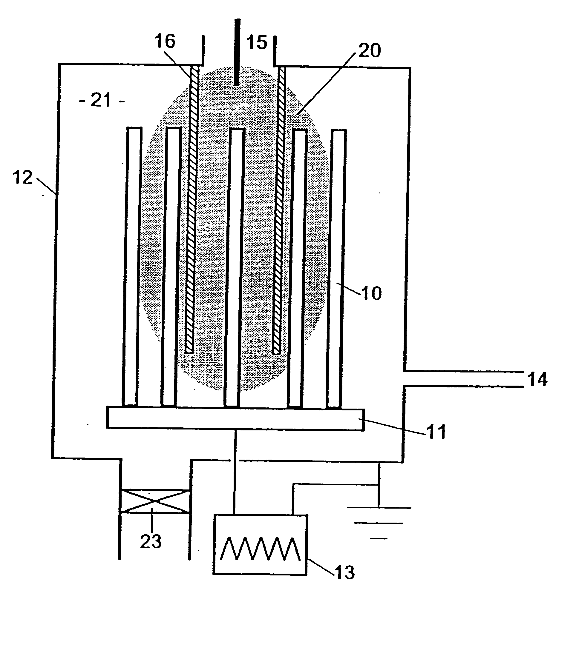
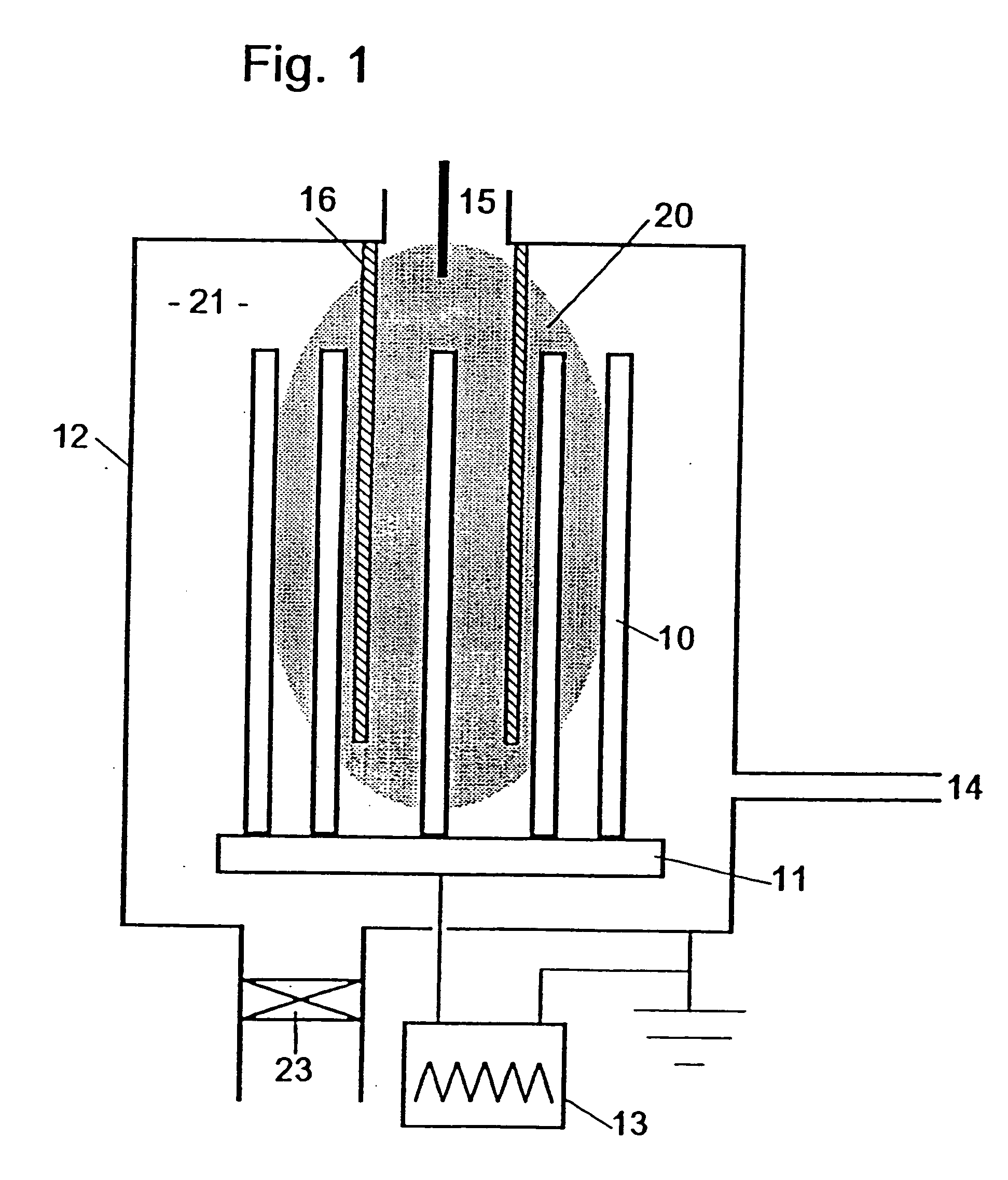
[0058] The manufacture of the structure takes place by means of reactive sputtering of targets made of metals (Me) and of metal carbides (MeC) in an atmosphere made up of a mixture of noble gas, such as argon, a sputter gas, and a gas containing carbon, such as acetylene and methane, as a reactive gas. The layers can be deposited using a device that differs from that shown in FIG. 3 by an additional sputter cathode. In a conventional manner, the gas flow is set constant in such a way that sputtering takes place in one method ste...
example 2
[0059] The multilayer system is made of C-(MeC) as a hard material, the metal preferably is tungsten, and of metal-free amorphous carbon containing hydrogen (a-C:H). The layer thicknesses are in the same ranges as in the first exemplary embodiment. The C—(MeC) layer is produced by reactive sputtering of (for example) a WC target. The additional carbon is supplied by acetylene or methane. The a-C:H layer is obtained using one of the plasma sources described above, such as an RF source, an MW source (see FIG. 3) or a hollow cathode source (see FIG. 4) in the atmosphere containing acetylene or methane. The deposition of the multilayer structure can be carried out using the device shown in FIG. 3, or using a device that differs from that shown in FIG. 4 by an additional sputter cathode.
example 3
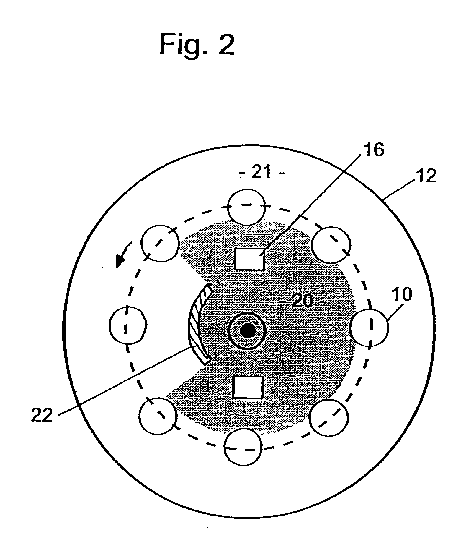
[0060] The multilayer system is made of a metal (Me) as a hard material and a-C:H. The metal preferably is selected from those named in Example 1. The layer thicknesses are in the same ranges as in the first exemplary embodiment. For the application of the layers, two gas chambers separated from one another are required, so that the metal can be applied by sputtering or vacuum metallization of metal in an atmosphere that does not contain carbon, and a-C:H can be deposited in an atmosphere containing methane or acetylene. The manufacture of the multilayer structure can be carried out using devices that operate similarly to those shown in FIGS. 6 and 7. A separation of the gas chambers also is possible (though not shown) in the device shown in FIG. 6. So that a large number of sources is not required for each layer, constructions of the devices are advantageous in which the specimens are led back to the beginning of the device after the application of the first two layers, and the app...
PUM
| Property | Measurement | Unit |
|---|---|---|
| thickness | aaaaa | aaaaa |
| thickness | aaaaa | aaaaa |
| thickness | aaaaa | aaaaa |
Abstract
Description
Claims
Application Information