
Tire for rear wheel of motorcycle

a rear wheel and motorcycle technology, applied in the direction of cycles, transportation and packaging, non-skid devices, etc., can solve the problems of driver's incompatibility, noise generation in cornering, complex load change of tire, etc., and achieve the effect of preventing great pitch sound and reducing the noise level of tir

Inactive Publication Date: 2005-05-12
SUMITOMO RUBBER IND LTD
View PDF5 Cites 40 Cited by
  • Summary
  • Abstract
  • Description
  • Claims
  • Application Information

AI Technical Summary

Benefits of technology

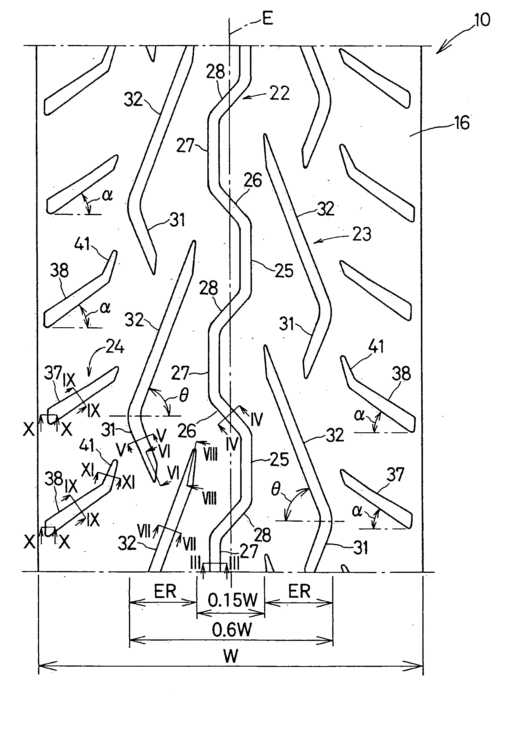
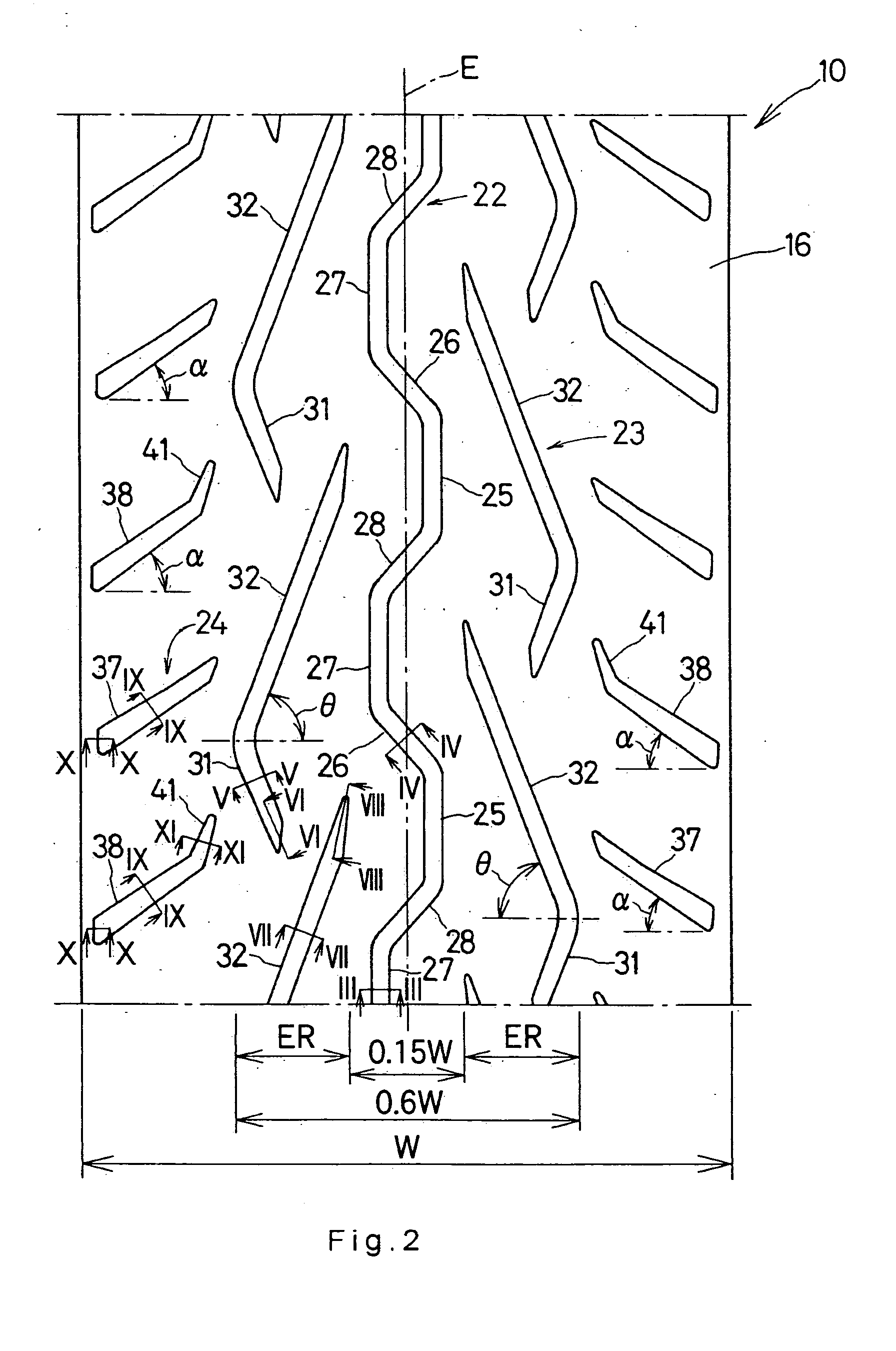
[0011] In the present invention, the rate of an area occupied by the long portion in the portion (contact surface) of the tread surface which comes in contact with a ground is reduced. The reason is that the intermediate groups are formed like the boomerang respectively and the angle θ of the long portion of each intermediate groove is set to be 45 degrees or more. Accordingly, a great pitch sound can be prevented from being generated when the tire rolls over the ground.
[0012] In a transition in which the motorcycle is switched from the straight running to the cornering, that is, in a process in which the portion of the tire coming in contact with the ground is changed from the center of the tread surface to the shoulder portion, the rate of the areas occupied by the long and short portions in the contact surface can be prevented from being changed suddenly. The reason is that the angle θ is set to be 75 degrees or less, and furthermore, each intermediate groove is provided in the region (0.15 W to 0.6 W). Also in the transition in which the motorcycle is switched from the straight running to the cornering, accordingly, a great pitch sound can be prevented from being generated suddenly when the tire rolls over the ground.
[0013] A difference in a noise level is not changed greatly between a sound generated when the motorcycle carries out the straight running and a sound generated when the motorcycle carries out the cornering. Moreover, there is an advantage that the generation of TGC (Tread Groove Cracking) is suppressed. The reason is that a waveform groove is provided on the center of the tread surface. The advantage is remarkable in the case in which a band ply constituting the tire particularly has a JLB (joint less band) structure (a structure in which a single and long band cord is wound upon a carcass). More specifically, if a straight groove is provided on the center of the tread surface, the direction of the groove almost overlaps with that of the band cord. Therefore, the portion on which the groove is formed is flexed easily. Accordingly, a distortion is generated repetitively in the portion on which the groove is formed so that the TGC is apt to be generated. On the other hand, the waveform groove is provided so that a continuous groove is not formed in the circumferential direction of the tire. As a result, the generation of the TGC is suppressed.
[0015] In the case in which a camber angle is great in the cornering of the motorcycle, that is, the motorcycle carries out high speed cornering, a grip force (particularly, a wet grip force) of the tire is maintained because the shoulder groove is provided. In addition, the shoulder groove is provided in such a manner that the angle is set to be α. Also in the transition in which the motorcycle is switched from the straight running to the cornering, therefore, a great pitch sound can be prevented from being generated suddenly from the tire.
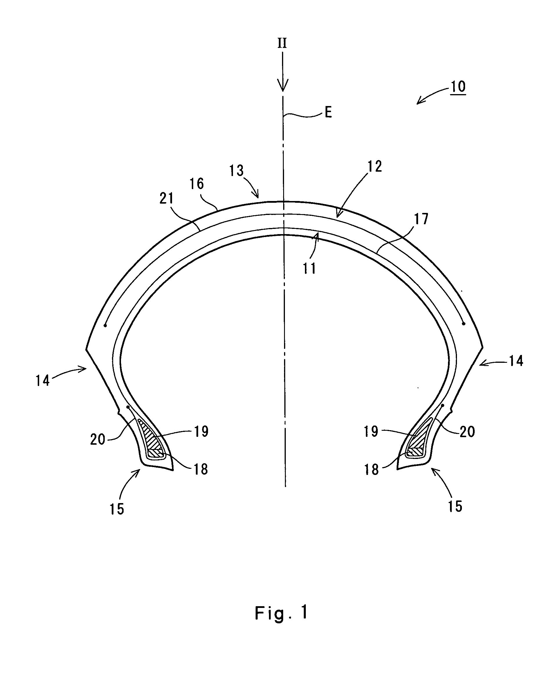
[0016] As described above, according to the present invention, the tread pattern is devised. In the straight running and cornering of the motorcycle and their transition, consequently, the noise level of the tire can be reduced and a silence can be maintained irrespective of a running manner.

Problems solved by technology

Accordingly, a load to be applied to the tire is changed complicatedly depending on the running manner of the motorcycle.
However, there is a problem in that the noise is generated in the cornering.
In some cases, however, a driver feels an incompatibility.

Method used


Image

  • Tire for rear wheel of motorcycle
  • Tire for rear wheel of motorcycle
  • Tire for rear wheel of motorcycle

Examples


example 1

[0073] A waveform groove, an intermediate groove and a shoulder groove are present on a tread surface. The long portion of the intermediate groove has an angle θ of 55 degrees. The region of the intermediate groove is 0.15 W to 0.6 W. The shoulder groove has an angle α of 25 degrees (α<θ).

example 2

[0074] A waveform groove, an intermediate groove and a shoulder groove are present on a tread surface. The long portion of the intermediate groove has an angle θ of 55 degrees. The region of the intermediate groove is 0.15 W to 0.6 W. The shoulder groove has an angle α of 30 degrees (α<θ).

example 3

[0075] A waveform groove, an intermediate groove and a shoulder groove are present on a tread surface. The long portion of the intermediate groove has an angle θ of 55 degrees. The region of the intermediate groove is 0.15 W to 0.6 W. The shoulder groove has an angle α of 40 degrees (α<θ).


PUM


Abstract

A tire (10) is employed for the rear wheel of a motorcycle. A tread surface (16) is provided with a waveform groove (22), an intermediate groove (23) and a shoulder groove (24). The waveform groove (22) meanders in a circumferential direction over the central portion of the tread surface (16). The intermediate groove (23) is provided on the left and right of the waveform groove (22) along the waveform groove (22). The intermediate groove (23) is present in a predetermined region (ER). The intermediate groove (23) is formed like a boomerang having a long portion (32) and a short portion (31). An angle θ with respect to the axial direction of the long portion (32) is 45 to 75 degrees. The shoulder groove (24) is provided on an outside in the axial direction of the tread surface (16). An angle α of the shoulder groove (24) is set to be 25 degrees≦α≦50 degrees and α<θ.

Description

[0001] This application claims priority on Patent Application No. 2003-380559 filed in Japan on Nov. 10, 2003. BACKGROUND OF THE INVENTION [0002] 1. Field of the Invention [0003] The present invention relates to a tire for a motorcycle. More particularly, the present invention relates to a structure of a tire to be employed for a rear wheel of a motorcycle. [0004] 2. Description of the Related Art [0005] When a motorcycle carries out cornering, a driver inclines the attitude of the motorcycle inward in a cornering direction. At this time, a tire comes in contact with a road surface to form a camber angle and generates a camber thrust on the contact surface of the tire. The camber thrust is resistant to a centrifugal force generated in the cornering of the motorcycle. The camber thrust realizes the stable cornering of the motorcycle. [0006] In order to generate the stable camber thrust, the tire is formed to draw a large arch in such a manner that a tread surface is convex in a radia...

Claims


Application Information

Patent Timeline
IPC IPC(8): B60C11/04
CPCB60C2200/10B60C2011/0369B60C11/13B60C11/0302
Inventor ITO, MAYUMI
Owner SUMITOMO RUBBER IND LTD
Learn More