
Elevator installation and monitoring system for an elevator installation

a monitoring system and elevator technology, applied in the direction of elevators, instruments, computer control, etc., can solve the problems of no identification of safety contacts, no diagnosis of whether one or more safety contacts are possible, no suitable measures can be taken by the control unit to control the elevator installation, etc., to improve the availability and improve the operation. the effect of safety

Active Publication Date: 2005-05-12
INVENTIO AG
View PDF10 Cites 34 Cited by
  • Summary
  • Abstract
  • Description
  • Claims
  • Application Information

AI Technical Summary

Benefits of technology

[0006] A purpose of the present invention is to eliminate the aforementioned problems and propose an elevator installation and a monitoring system for an elevator installation with improved operating safety and improved availability.
[0010] In an advantageous further development of the present invention, the bus node is constructed passively so that the status of the bus node can be interrogated by the control unit. By this means the capital outlay for realization of the bus node remains small.
[0011] In an alternative further development of the present invention, the bus node is constructed actively. By this means the bus node transmits the status of the assigned sensor to the control unit. Although bus nodes of this type are constructed more elaborately, with active bus nodes of this type the control unit can be constructed more decentralized and the complexity of the control unit can be reduced.
[0014] In a further advantageous development of the present invention, it is envisaged that the bus node, when transmitting the status to the control unit, also transmits an identification. This avoids one bus node from transmitting a status signal for another bus node which is possibly incorrect.

Problems solved by technology

Disadvantageous with such manner of connecting the safety contacts is that no diagnosis is possible as to whether one or more safety contacts are faulty.
Consequently, no suitable measures can be taken by the control unit to control the elevator installation.
Moreover, with such manner of connecting the safety contacts, no identification of the safety contacts is possible, and it is also impossible to transmit further information about intermediate statuses or counter values, etc.
Disadvantageous with such built-in redundancy is that a bus node can also transmit a faulty signal to the control even though the sensor assigned to this bus node detects a fault-free or operable status of the elevator installation and no faulty status is in fact present.

Method used


Image

  • Elevator installation and monitoring system for an elevator installation
  • Elevator installation and monitoring system for an elevator installation
  • Elevator installation and monitoring system for an elevator installation

Examples


Embodiment Construction

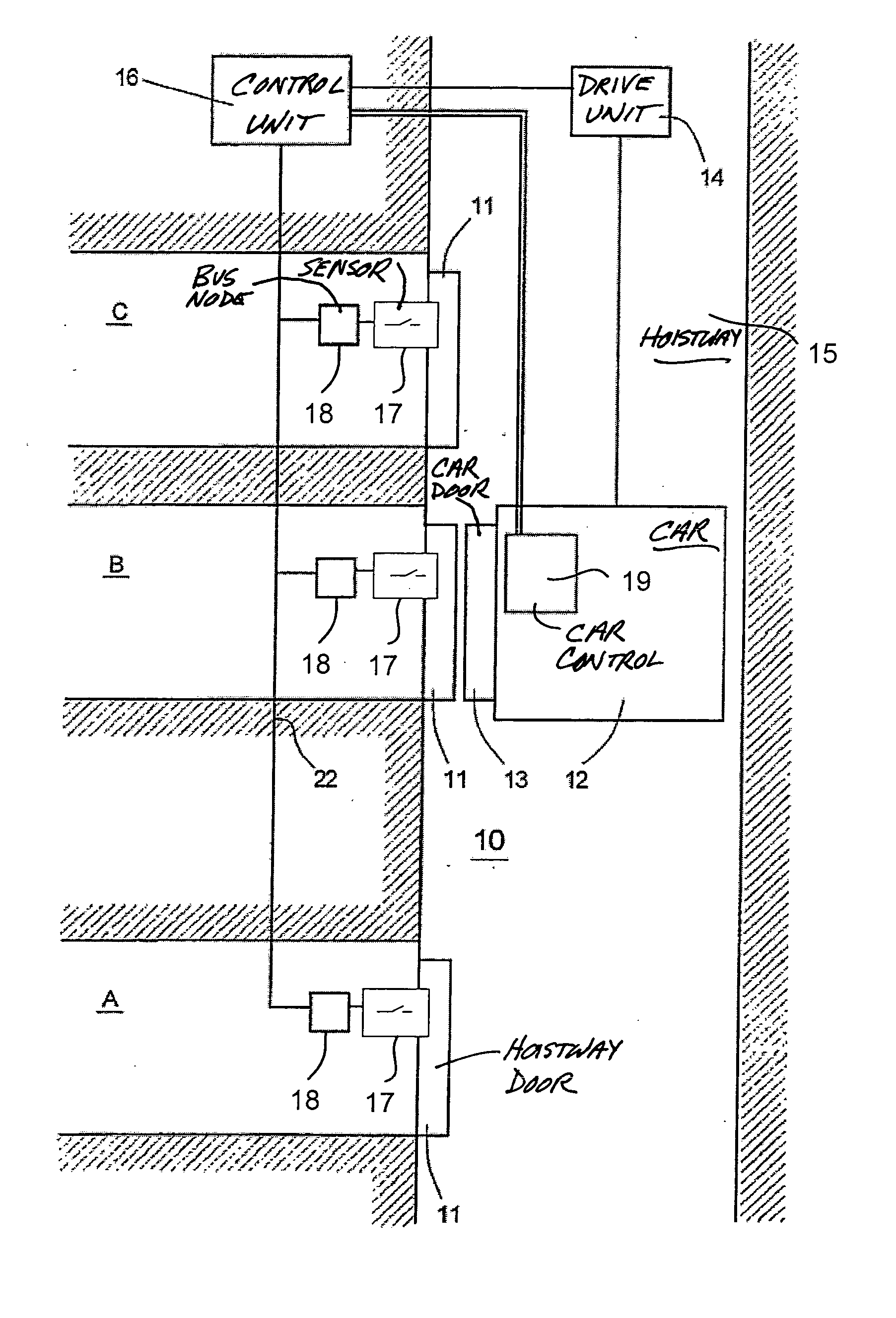
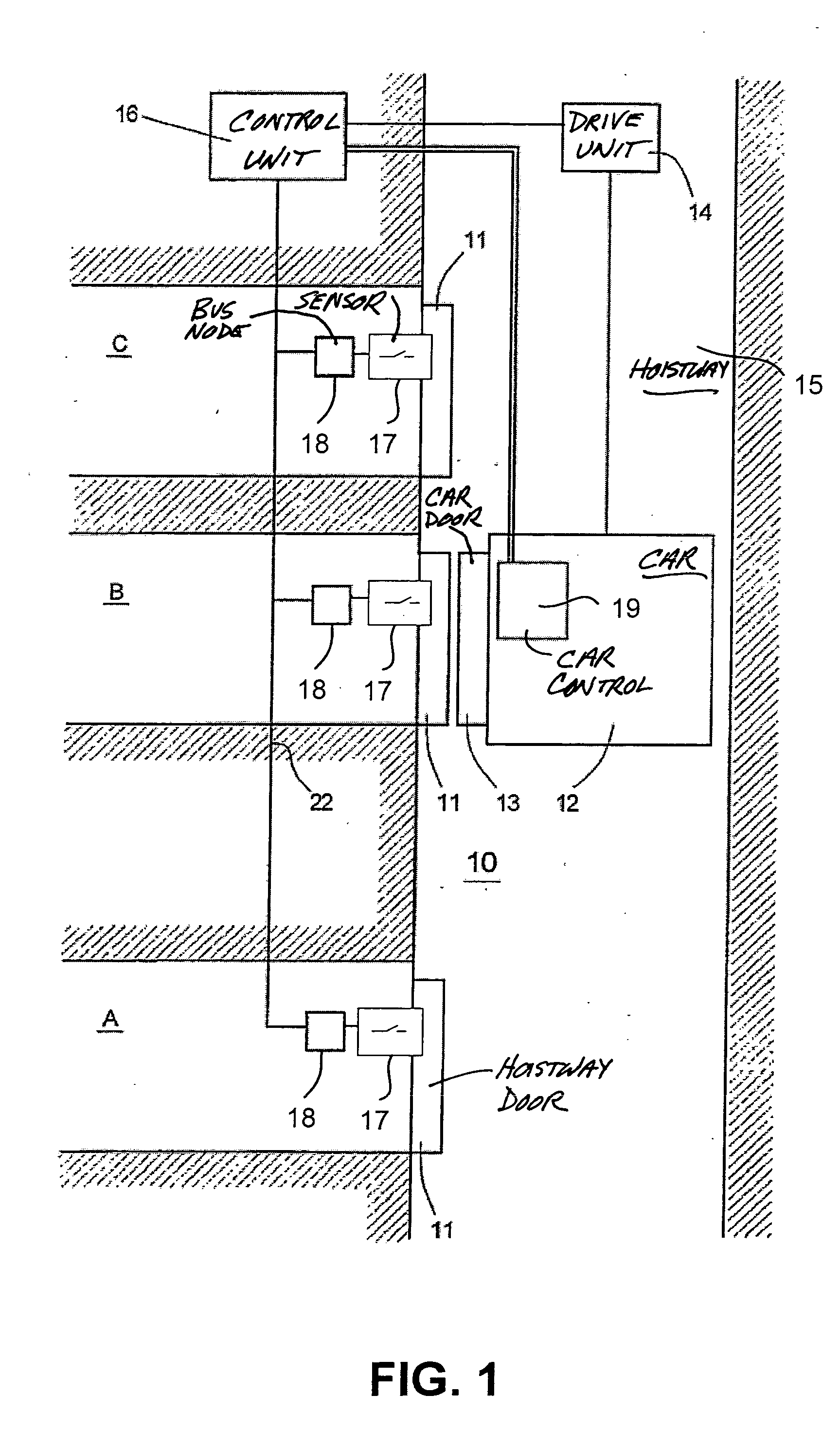
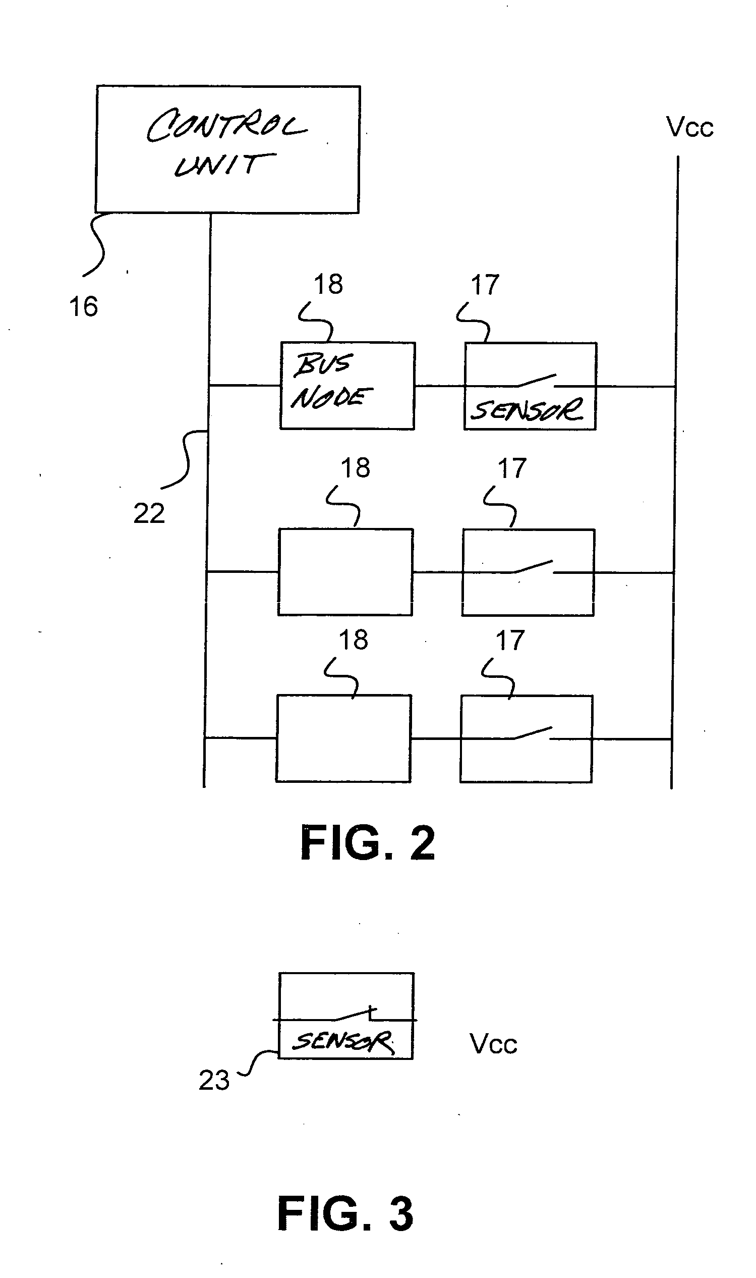
[0021] Represented in FIG. 1 is an elevator installation 10 with an elevator car 12 that is moved in an elevator hoistway 15. The elevator car 12 is moved between floors A, B, and C of a building by a drive unit 14 in the elevator hoistway 15. The elevator car 12 has car doors 13 and a car control 19. Arranged on each of the individual floors A, B, C are hoistway doors 11. Arranged on each hoistway door 11 is at least one sensor 17 which is connected to an assigned bus node 18, the bus node 18 being connected via a data bus 22 to a control unit 16. The respective sensors 17 on the floors A, B, C are constructed as circuit-completing switches which when actuated are closed. The control unit 16 controls the elevator installation 10, and for this purpose is connected to the drive unit 14, to the car control 19, and via the data bus 22 and the bus nodes 18 to the sensors 17 assigned to them. The sensors 17 form a so-called safety circuit. The control unit 16 can also be a door-monitorin...


PUM


Abstract

An elevator installation with an elevator car moveable in an elevator hoistway by means a drive unit is controlled by a control unit. Sensors monitor the status of the elevator installation and are each connected via an assigned bus node to a data bus and thereby connected to the control unit. In order to obtain improved operational safety and improved availability, each sensor controls a voltage supply of the associated bus node.

Description

BACKGROUND OF THE INVENTION [0001] The present invention relates to an elevator installation with an elevator car, which by means of a drive unit can be caused to move in an elevator hoistway. The elevator installation can be controlled by a control unit. To monitor the status of the elevator installation sensors are also provided, each of which is connected via an assigned bus node to a data bus and thereby to the control unit. In addition, the invention relates to a monitoring system for an elevator installation, which comprises several bus nodes. The bus nodes are connected via a data bus to a control unit, there being assigned to each bus node a sensor. The sensor connected to the bus node is provided for the purpose of monitoring the status of the elevator installation. [0002] In prior art elevator installations, safety contacts are used to detect the status of the elevator installation. Conventional elevator installations use safety contacts which are connected to each other i...

Claims


Application Information

Patent Timeline
IPC IPC(8): B66B1/34B66B3/00B66B5/00B66B5/02
CPCB66B5/0018
Inventor ANGST, PHILIPP
Owner INVENTIO AG
Learn More