Conveyor system having width adjustment unit

a conveyor system and width adjustment technology, applied in the field of conveyor systems, can solve the problems of static electricity damage to the alignment layer, degrade the injection of liquid crystal materials, and disadvantages of conveyor systems such as those illustrated in fig. 3, and achieve the effect of minimizing the failure of the operation of the conveyor system and minimizing the failure of the operation

Inactive Publication Date: 2005-05-12
LG PHILIPS ELECTRONICS CO LTD
View PDF40 Cites 11 Cited by
  • Summary
  • Abstract
  • Description
  • Claims
  • Application Information

AI Technical Summary

Benefits of technology

[0036] An advantage of the present invention is to provide a conveyor system capable of automatically adjusting a width, and to minimize operation failure due to foreign matter.
[0037] Additional advantages, and features of the invention will be set forth in part in the description which follows and in part will become apparent to those having ordinary skill in the art upon examination of the following or may be learned from practice of the invention. These advantages of the invention may be realized and attained by the structure particularly pointed out in the written description and claims hereof as well as the appended drawings.
[0038] To achieve these advantages and in accordance with the purpose of the invention, as embodied and broadly described herein, a conveyor system includes a transfer unit for transferring goods; conveyor plates provided at both sides of the transfer unit, and guiding the goods by supporting both sides of the goods; and a width adju

Problems solved by technology

Conveyor systems such as those illustrated in FIG. 3, however, are disadvantageous for the following reasons.
Static electricity damages the alignment layer and degrades the injected liquid crystal material.
However, in case of the aforementioned width adjustment unit, a pitch is inconstant since the shaft 3d and the screw nut 3c are not processed precisely.
As a result, it is difficult to determine a precise position, whereby the width of the conveyor plate is inconstant.
Also, if the shaft and the screw nut are processed precisely

Method used


Image

  • Conveyor system having width adjustment unit
  • Conveyor system having width adjustment unit
  • Conveyor system having width adjustment unit

Examples


Embodiment Construction

[0054] Reference will now be made in detail to embodiments of the present invention, examples of which are illustrated in the accompanying drawings. Wherever possible, the same reference numbers will be used throughout the drawings to refer to the same or like parts.

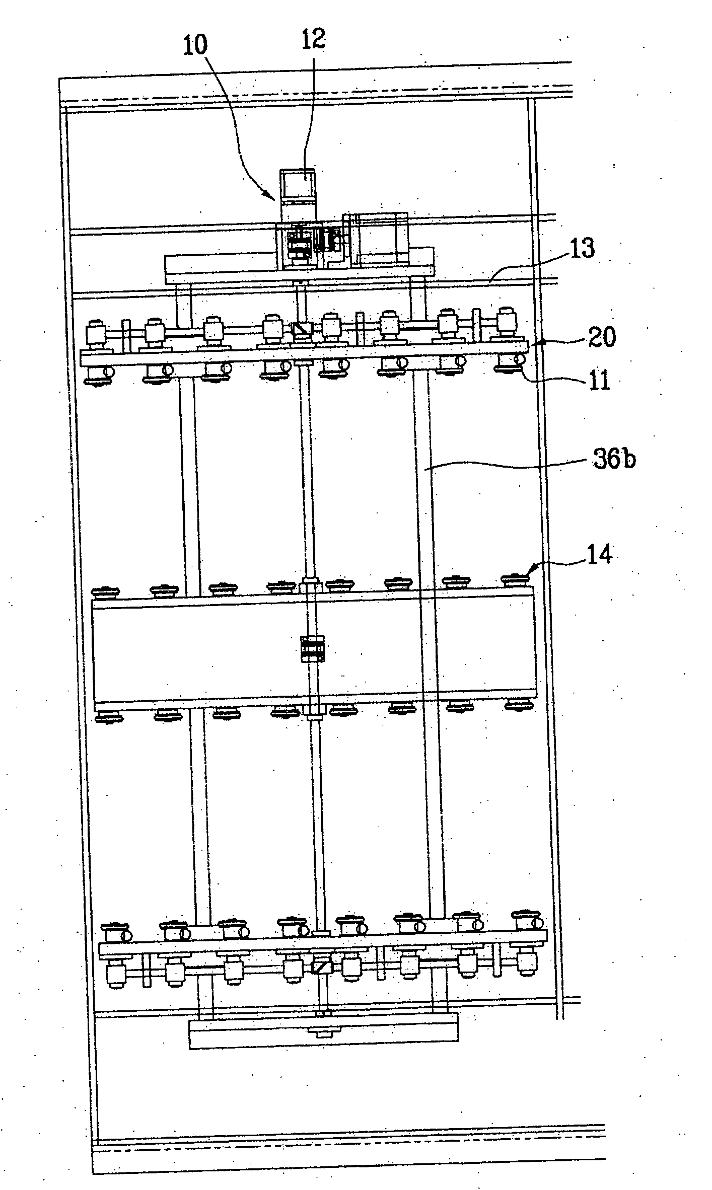
[0055]FIG. 5 illustrates a front view of a conveyor of a conveyor system for conveying goods, such as a liquid crystal panel, according to the present invention.

[0056] Referring to FIG. 5, a liquid crystal panel 500, including TFT and color filter substrates bonded to each other, may be arranged on a rotating roller 700 of a conveyor system.

[0057] In one aspect of the present invention, the liquid crystal panel may prepared by injecting liquid crystal material between first and second substrate including TFT and color filter substrates, respectively, and cutting the injected first and second substrates (e.g., using a cutting wheel).

[0058] In one aspect of the present invention, the cutting wheel may comprise a materi...


PUM


Abstract

A conveyor system is disclosed, having a width adjustment unit capable of adjusting a width according to the size of goods to transfer semiprocessed goods in the process line, which includes a transfer unit for transferring goods; conveyor plates provided at both sides of the transfer unit, and guiding the goods by supporting both sides of the goods; and the width adjustment unit including a wire connected with the conveyor plates, a driving pulley operating the wire, and a driven connected with the wire.

Description

[0001] This application is a Continuation-In-Part (CIP) of application Ser. No. 10 / 303,922 filed Nov. 26, 2002, which is hereby incorporated by reference as if fully set forth herein. This application claims the benefit of the Korean Application No. P2002-033500 filed on Jun. 15, 2002 and Korean Application No. P2003-67827, filed on Sep. 30, 2003, both of which are also hereby incorporated by reference.BACKGROUND OF THE INVENTION [0002] 1. Field of the Invention [0003] The present invention relates to a conveyor system for conveying liquid crystal panels, more particularly the present invention relates to a conveyor system having a width adjustment unit. [0004] 2. Discussion of the Related Art [0005] Generally, liquid crystal displays are devices that display images using liquid crystal cells arranged in a matrix pattern. Data signals, representative of image information, may be used to selectively control the light transmittance of each of the liquid crystal cells. [0006] Liquid cr...

Claims


Application Information

Patent Timeline
IPC IPC(8): B65G13/12B65G39/02B65G49/06
CPCB65G13/12B65G2249/02B65G49/064B65G39/02
Inventor UH, JI HEUMCHAE, KYUNG SULEE, JEONG JOONSONG, HYUN HOLEE, HONG SEOK
Owner LG PHILIPS ELECTRONICS CO LTD
Why Eureka
Try Eureka