Method of forming wirings for tile-shaped elements, structures of wirings for tile-shaped elements, and electronic equipment

a technology of wiring and tile, applied in the direction of conductive pattern formation, printed circuit non-printed electric component association, semiconductor/solid-state device details, etc., can solve the problems of substantial time and material cost, substantially large manufacturing cost, so as to reduce the waste of liquid material, excellently formed, and high reliability

Inactive Publication Date: 2005-05-12
SEIKO EPSON CORP
View PDF4 Cites 26 Cited by
  • Summary
  • Abstract
  • Description
  • Claims
  • Application Information

AI Technical Summary

Benefits of technology

[0017] In the wiring forming method for a tile-shaped element in accordance with an exemplary aspect of the invention, the liquid material may be applied to the wiring region by a screen printing method or a pad printing method. It is noted here that the screen printing method is a printing method in which a screen having a pattern formed with presence or absence of opening sections is placed on a base material (substrate) to be printed and paste (liquid material) is adhered only to openings by using the opening sections. Even in the screen printing method, a non-contact coating by using a dispenser is possible. The screen printing method can reduce waste of liquid material, compared to the case where a spin coat method is used. The pad printing method is a technique in which grooves are cut in reverse images of wiring regions in, for example, a metal plate. Liquid material is printed in the grooves. A pad made of silicon rubber or the like is pressed against the plate, and the liquid material is transferred onto the pad. The pad is pressed against a specified area on a substrate (member to be printed) to thereby complete the transfer, so that the liquid material is coated on a wiring region. By using the pad printing method, electrical wirings can be excellently formed in wiring regions with irregularities, for example, when the electrical wirings are formed after a tile-shaped element is bonded to a substrate.
[0018] The wiring forming method for a tile-shaped element in accordance with an exemplary aspect of the invention may be conducted after the tile-shaped element is bonded to the substrate. According to an exemplary aspect of the invention, the liquid material may be continuously coated to cover the electrode of the tile-shaped element and the electrode of the substrate, to thereby form electrical wirings. Accordingly, even when the position of the tile-shaped element slightly deviates when the tile-shaped element is bonded to the substrate, the electrode of the tile-shaped element and the electrode of the substrate can be electrically connected in a highly reliable manner by, for example, adjusting the coating position.
[0019] A wiring structure for a tile-shaped element in accordance with an exemplary aspect of the invention pertains to a wiring structure for a tile-shaped element defining a component of a structure in which a tile-shaped element having at least an electrode and a tile configuration is bonded to a substrate having at least an electrode, and having an electrical wiring that electrically connects the electrode of the tile-shaped element to an electrode of the substrate. The electrical wiring is formed from a binder material, and the binder material is composed of one of epoxy, acrylic resin and polyimide. According to an exemplary aspect of the invention, the mechanical strength of the electroconductive film composing the electrical wiring can be enhanced and adhesion between the electroconductive film

Problems solved by technology

However, when the electrical wiring is formed by aerial wiring, such as wire bonding, the wiring work requires substantial time.
In particular, minute wiring work is difficult and results in a substantially large manufacturing cost.
When the electrical wiring is formed by using

Method used


Image

  • Method of forming wirings for tile-shaped elements, structures of wirings for tile-shaped elements, and electronic equipment
  • Method of forming wirings for tile-shaped elements, structures of wirings for tile-shaped elements, and electronic equipment
  • Method of forming wirings for tile-shaped elements, structures of wirings for tile-shaped elements, and electronic equipment

Examples


first exemplary embodiment

[0040] A wiring forming method for a tile-shaped element and a wiring structure for a tile-shaped element in accordance with a first exemplary embodiment of the invention are described below. As an example of a tile-shaped element in accordance with the present exemplary embodiment, a micro tile-shaped element in a minute tile configuration is described. However, the invention is not limited to this, and can be applied to a tile-shaped element that is not minute. First, a wiring forming method for a tile-shaped element and a wiring structure for a tile-shaped element in accordance with the first exemplary embodiment of the invention are described with reference to FIGS. 1A-B and FIGS. 2A-B.

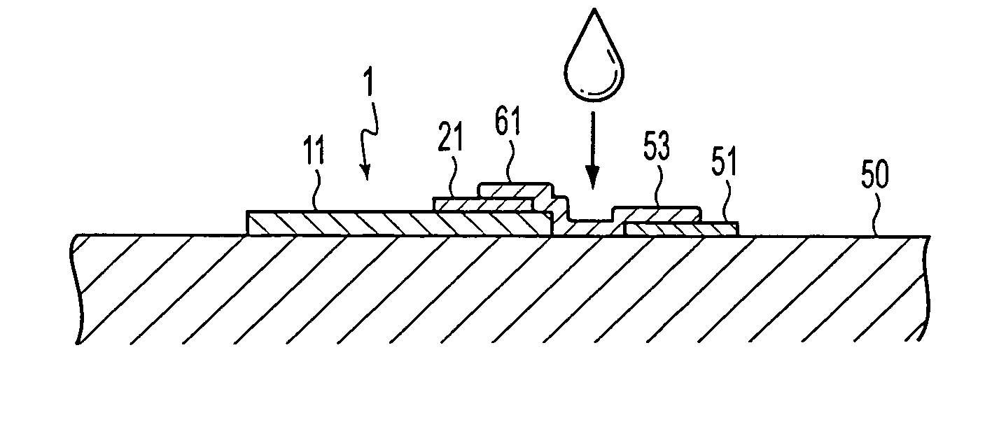
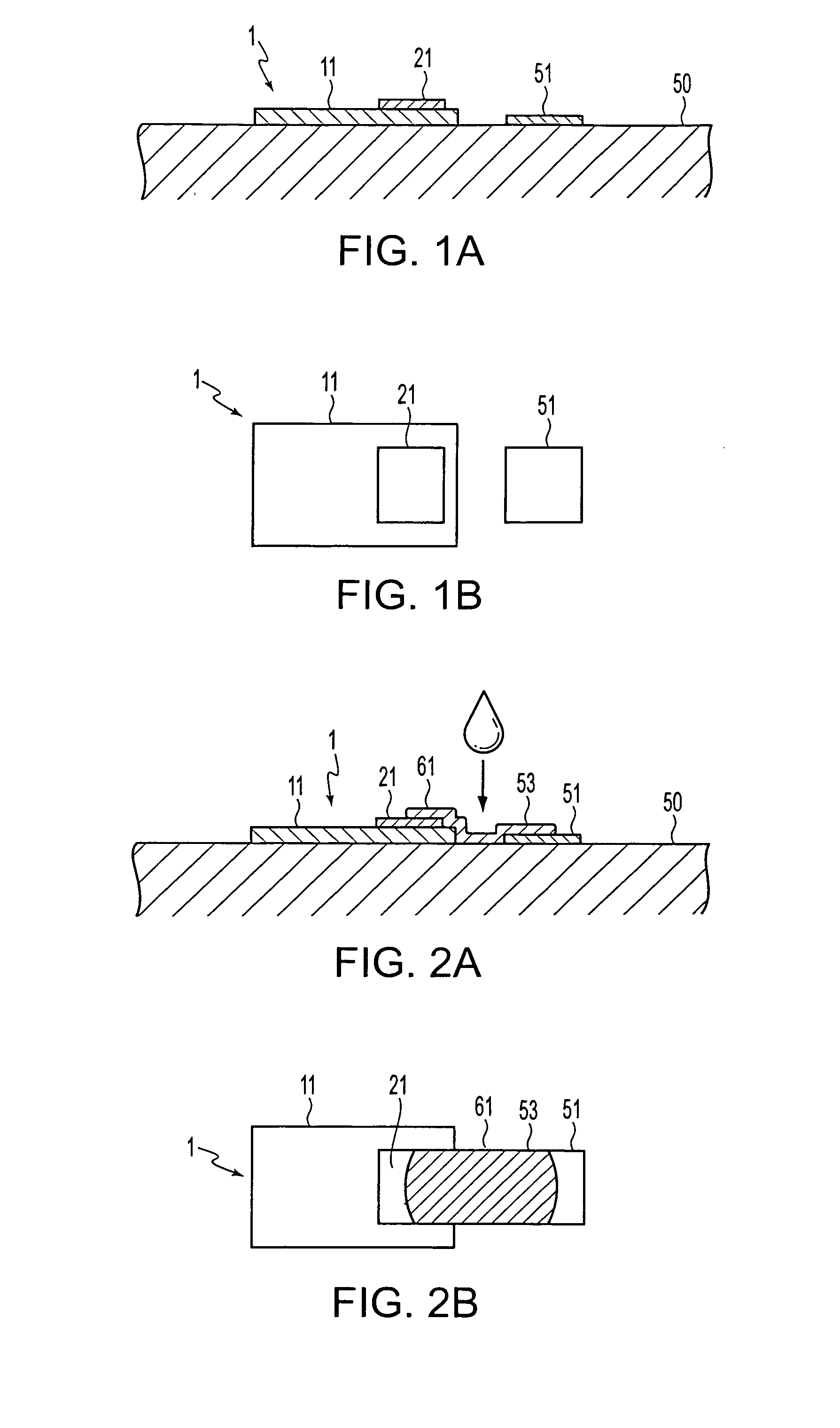
[0041] FIGS. 1A-B are schematics in which a micro tile-shaped element is bonded to a final substrate. A micro tile-shaped element 1 is equipped with a tile section 11 in a tile configuration and an electrode 21 provided on an upper surface of the tile section 11. The tile section 11 may have a fu...

examples of application

METHOD

[0050] Next, examples of the method of applying the liquid material 53 to the wiring region 61 are described. For example, a method in which the liquid material 53 is once applied to the entire surface of the final substrate 50 including the surface of the minute tile element 1, and then, the liquid material 53 applied on areas other than the wiring region 61 is removed, to thereby coat the liquid material only on the wiring region 61, can be used. However, according to this method, the amount of the liquid material 53 that becomes wasted is large. Thus, it is desirable to use a method in which the liquid material 53 is initially, selectively applied only to the wiring region 61.

[0051] A droplet discharge method to jet the liquid material 53 as droplets from an ink jet nozzle, that may be used with, for example, an ink-jet printer, or the like, can be used as the method to selectively apply the liquid material 53. Moreover, the liquid material 53 may be discharged as droplets...

second exemplary embodiment

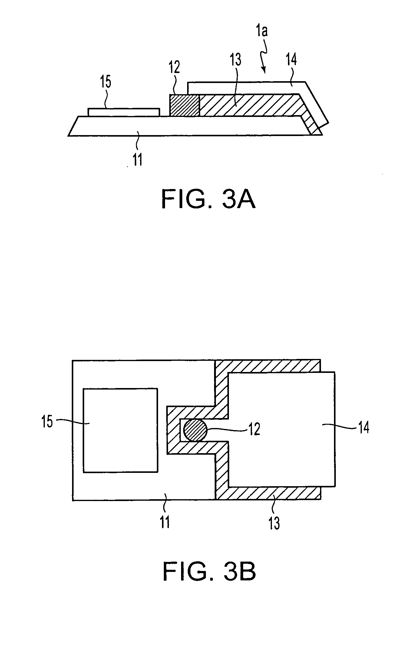
[0055] Next, a wiring forming method for a tile-shaped element and a wiring structure for a tile-shaped element in accordance with a second exemplary embodiment of the invention are described below with reference to FIGS. 3A-B through FIGS. 5A-B. First, a micro tile-shaped element 1a to which the wiring forming method of the present exemplary embodiment is applied is described. FIGS. 3A-B show an example of a micro tile-shaped element in accordance with the second exemplary embodiment. The micro tile-shaped element 1a is a minute semiconductor element in a tile configuration. The micro tile-shaped element 1a is formed from a plate-like member having a thickness of 20 μm or less, and a size in width and length of several ten μm to several hundred μm. In a method for manufacturing the micro tile-shaped element 1a, a sacrificial layer is formed on a semiconductor substrate (first substrate), and a functional layer (electronic functional section) that defines the micro tile-shaped eleme...


PUM


Abstract

Methods are provided to form wirings for tile-shaped elements, structures of wirings for tile-shaped elements, and electronic equipment, with which highly reliable electrical wirings having minute wiring patterns can be formed. In wiring forming method for a tile-shaped element, which is used, when a circuit device is formed by connecting a tile-shaped element having at least an electrode and a tile configuration to a final substrate having at least an electrode, to form an electrical wiring that electrically connects the electrode of the tile-shaped element to the electrode of the final substrate, liquid material including electro conductive material is applied to at least a part of a wiring region that is a region where the electrical wiring is formed on at least one of surfaces of the final substrate and the tile-shaped element.

Description

BACKGROUND OF THE INVENTION [0001] 1. Field of Invention [0002] Exemplary aspects of the invention relate to methods of forming wirings for tile-shaped elements, structures of wirings for tile-shaped elements, and electronic equipment. [0003] 2. Description of Related Art [0004] The related art includes epitaxial lift-off (ELO) methods, in which semiconductor elements formed on a substrate are diced into micro tile elements (semiconductor elements), each in the shape of a micro tile configuration, and separated from the substrate. The micro tile element is handled and attached to an optional substrate (final substrate), thereby forming a substrate equipped with a thin film device (circuit device). See Japanese Laid-open Patent Application 2000-58562. SUMMARY OF THE INVENTION [0005] In the related art, an electrode (terminal) of the micro tile element is connected with an electrical wiring to an electrode (terminal) of a circuit that is provided on the final substrate. However, for e...

Claims


Application Information

Patent Timeline
IPC IPC(8): H01L21/288H05K3/32H01L21/60H05K1/18H05K3/10
CPCB82Y30/00H01L2924/1305H01L24/24H01L24/82H01L24/83H01L33/0079H01L2221/68354H01L2221/68359H01L2221/68368H01L2224/24011H01L2224/24225H01L2224/24226H01L2224/76155H01L2224/83001H01L2224/83192H01L2224/838H01L2224/92244H01L2924/01005H01L2924/01013H01L2924/01015H01L2924/01029H01L2924/01046H01L2924/01047H01L2924/0105H01L2924/01075H01L2924/01078H01L2924/01079H01L2924/01082H01L2924/0781H01L2924/09701H01L2924/10336H01L2924/14H01L2924/19041H01L2924/19042H01L2924/00011H01L21/288H01L2224/82102H01L2924/00013H01L2924/12041H01L2924/0665H01L2924/014H01L2924/01033H01L2924/01006H01L2224/29298H01L2224/2919H01L24/29H01L2924/00H01L2924/3512H01L2224/29099H01L2224/29199H01L2224/29299H01L2224/2929H01L2924/12042H01L2924/12043H01L33/0093
Inventor KONDO, TAKAYUKI
Owner SEIKO EPSON CORP
Why Eureka
Try Eureka