Gasket for acid waste couplings

a gasket and acid waste technology, applied in the direction of fluid pressure sealing joints, pipe joints, sleeves/socket joints, etc., can solve the problems of acid waste disposal system pipe joints not being able to stand the deterioration effect, prone to breakage and leakage, and the clamping assemblies mentioned above are deficient in sealing pipe joints. , to achieve the effect of enhancing the joining of slightly oversized pipes

Inactive Publication Date: 2005-05-12
TARARA JAMES A
View PDF3 Cites 17 Cited by
  • Summary
  • Abstract
  • Description
  • Claims
  • Application Information

AI Technical Summary

Benefits of technology

[0017] The critical novelty of the present invention lies in the construction of the thin sealing gasket and the transition couplings. Each comprises an elastomeric core and a lubricious and acid-resistant polymer face. In the preferred embodiment, this lubricious and acid resistant polymer is PTFE, commonly known as teflon, although several other materials, such as polyethylene, polypropylene, delryn, and nylon would serve the purpose with approximate equivalence. On the sealing gasket, this PTFE face covers at least the inner

Problems solved by technology

It is found that such clamping assemblies as mentioned above are deficient in sealing pipe joints of acid waste disposal systems.
Those sealing materials chosen in the above mentioned assemblies for their elastomeric properties provide optimal initial sealing, but are not capable of withstanding the deteriorating effects of the acid waste and are prone to break dow

Method used


Image

  • Gasket for acid waste couplings
  • Gasket for acid waste couplings
  • Gasket for acid waste couplings

Examples


Embodiment Construction

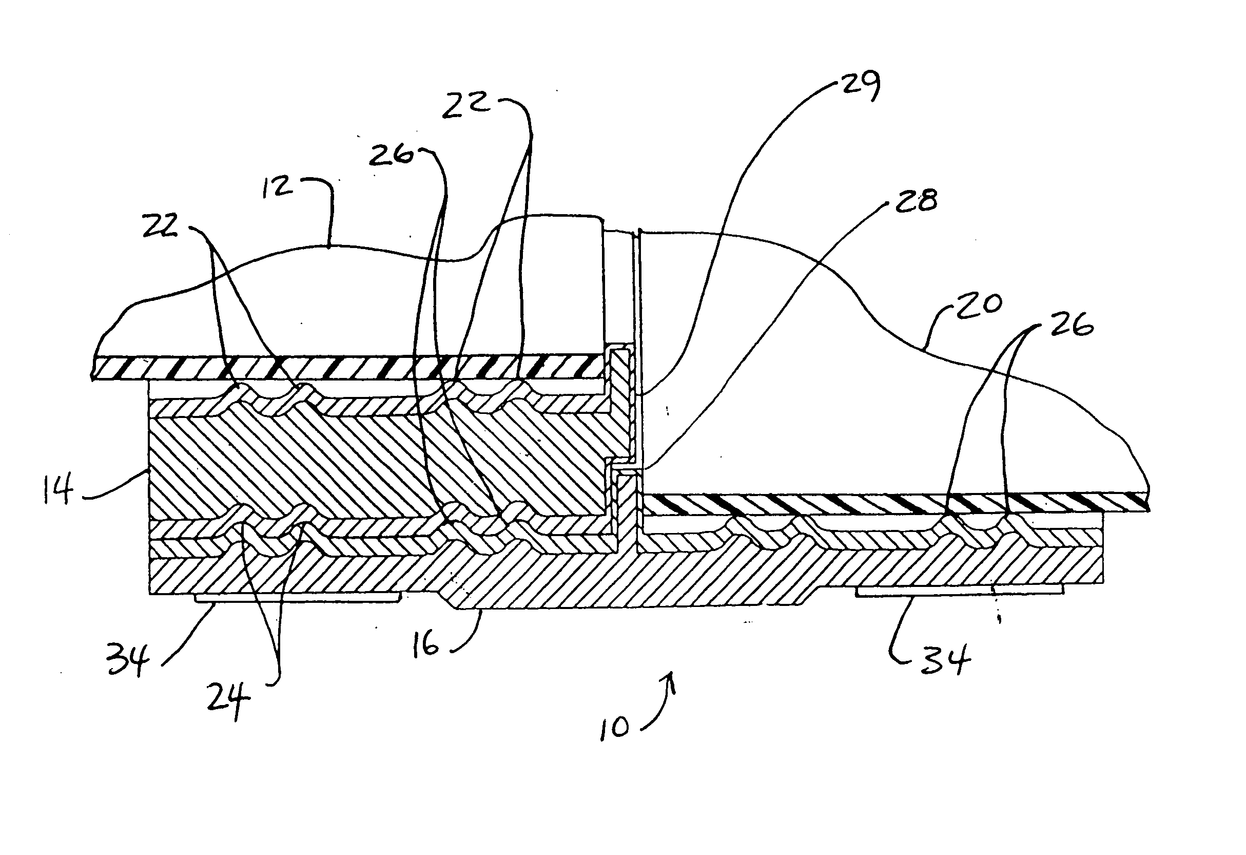
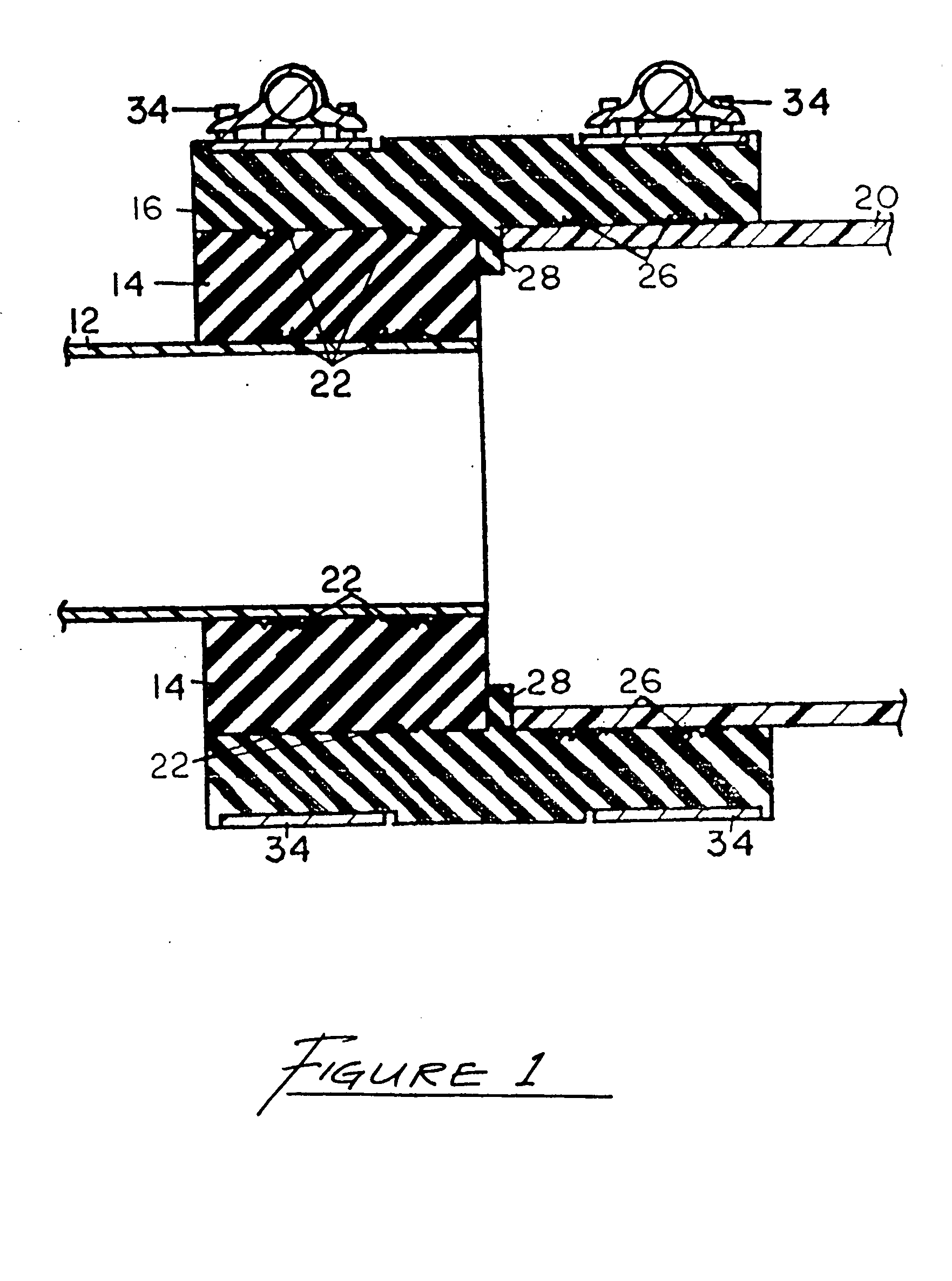
[0024]FIG. 1 shows the pipe-clamp assembly of the invention 10 with a pipe 12 of reduced diameter and a pipe 20 of larger diameter each at one end of an improved pipe clamp assembly 10 which comprises a transition pipe coupling 14, a thin sealing gasket 16 and an overlapping metal clamping band 18 having an end 38. The transition pipe coupling 14 contains a pair of sealing gasket ridges 22 on the inner diameter surface thereof and a pair of generally parallel circumferential grooves 24 on the outer diameter surface thereof. The thin sealing gasket 16 has two pairs of sealing gasket ridges 26 extending circumferentially around the internal surface with a pair of ridges extending on each side of an extending centrally disposed lip 28. The sealing gasket 16 includes generally disposed centrally raised ridge 30 about the external surface which fits within the central raised portion 32 of the metal clamping band. The metal clamping band has band straps 34 on either side adapted to be thr...


PUM


Abstract

A pipe clamp assembly for joining pipe ends of the same or different diameters in a linear relationship for use in acid waste disposal systems. The clamp assembly comprises a flexible clamping band which surrounds the pipe ends to be joined, an elastomeric, circumferential, thin sealing gasket beneath the clamping band and, when joining pipe ends of differing diameters, an elastomeric, circumferential transition coupling within the sealing gasket, the transition coupling having grooves on the exterior surface to engage sealing beads on the interior surface of the sealing gasket, to form a sealing relationship between the exterior surface of the transition coupling and the interior surface of the sealing gasket, and circumferential sealing beads on the interior surface of the transition coupling, to form a sealing relationship with the exterior surface of the reduced diameter joint or pipe to be sealed, thereby providing a clamp assembly adapted to clamp together pipes or joint ends of different diameters. The sealing surfaces of the sealing gasket and transition coupling are layered with teflon to ease assembly, improve sealing, and increase reliability for use in acid waste disposal systems.

Description

FIELD OF THE INVENTION [0001] The present invention is generally directed toward pipe joint clamping assemblies, and more specifically toward such clamping assemblies intended for use in the joining of variously sized pipes for use in acid waste disposal systems. BACKGROUND OF THE INVENTION [0002] Pipe-clamping assemblies are typically employed for the installation and joining of rigid pipes and pipe joints. Such pipe-clamping assemblies clamp together the pipe ends or joint ends in a fluid-tight sealing, aligned relationship. A pipe-clamping assembly may be needed for pipes of various sizes and dimensions. A variety of pipe-clamping assemblies has been proposed, and in particular the pipe-clamping assembly disclosed in U.S. Pat. No. 4,101,151, has provided a simple, easily manufactured, effective clamping assembly which provides for slight variations in external pipe diameters, which patent is hereby incorporated by reference. [0003] The pipe-clamping assembly of the '151 patent co...

Claims


Application Information

Patent Timeline
IPC IPC(8): F16L21/00F16L21/02F16L21/06
CPCF16L21/005F16L25/14F16L21/06F16L21/022
Inventor TARARA, JAMES A.
Owner TARARA JAMES A
Why Eureka
Try Eureka