[0008] In contrast, the object of the present invention is to reduce the
system costs significantly compared with the known art by providing a simply constructed headlight unit without wearing parts, thus ensuring trouble-free operation with high operating safety. As regards illumination of the driving lane while negotiating a curve, the headlight unit is designed to achieve improved illumination, corresponding substantially to that of straight-ahead driving; the purpose is to prevent, even if the vehicle is extremely inclined on the curve, an upwardly directed
light cone that blinds the oncoming traffic.
[0010] To achieve better illumination, especially while negotiating a curve, it is expedient to
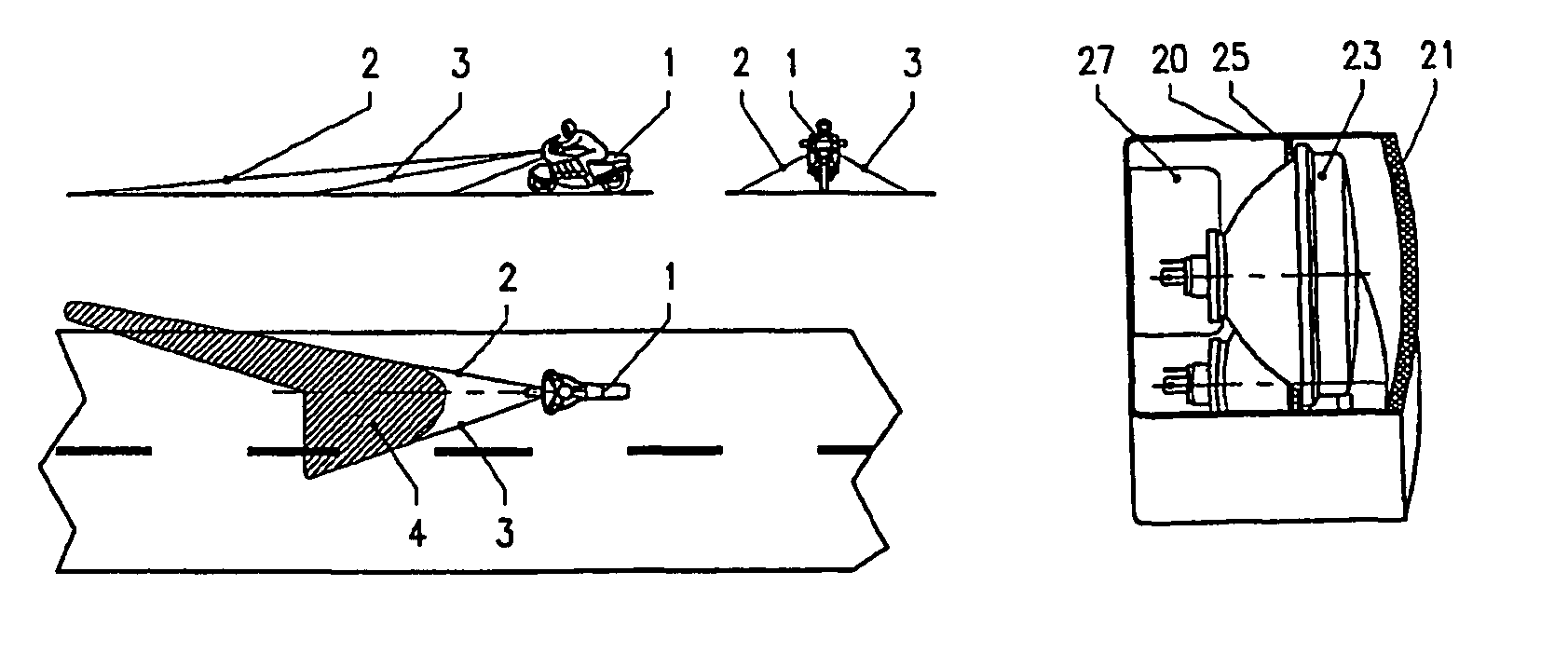
mount the laterally disposed headlights lower than the middle headlight relative to the upright orientation of the vehicle, in such a way that a bow-shaped headlight bar bent downward on both sides is formed. Alternatively, however, other headlight arrangements are also conceivable within the inventive headlight unit, such as an arrangement of all headlights at the same height, an inversely bowed arrangement thereof or even an asymmetric arrangement of headlights. For example, it may be expedient, depending on whether the vehicle will be operated in traffic driving on the right or left, to increase the number of headlights on the right or left side compared with the respective other side, in order to achieve better illumination across the driving lane.
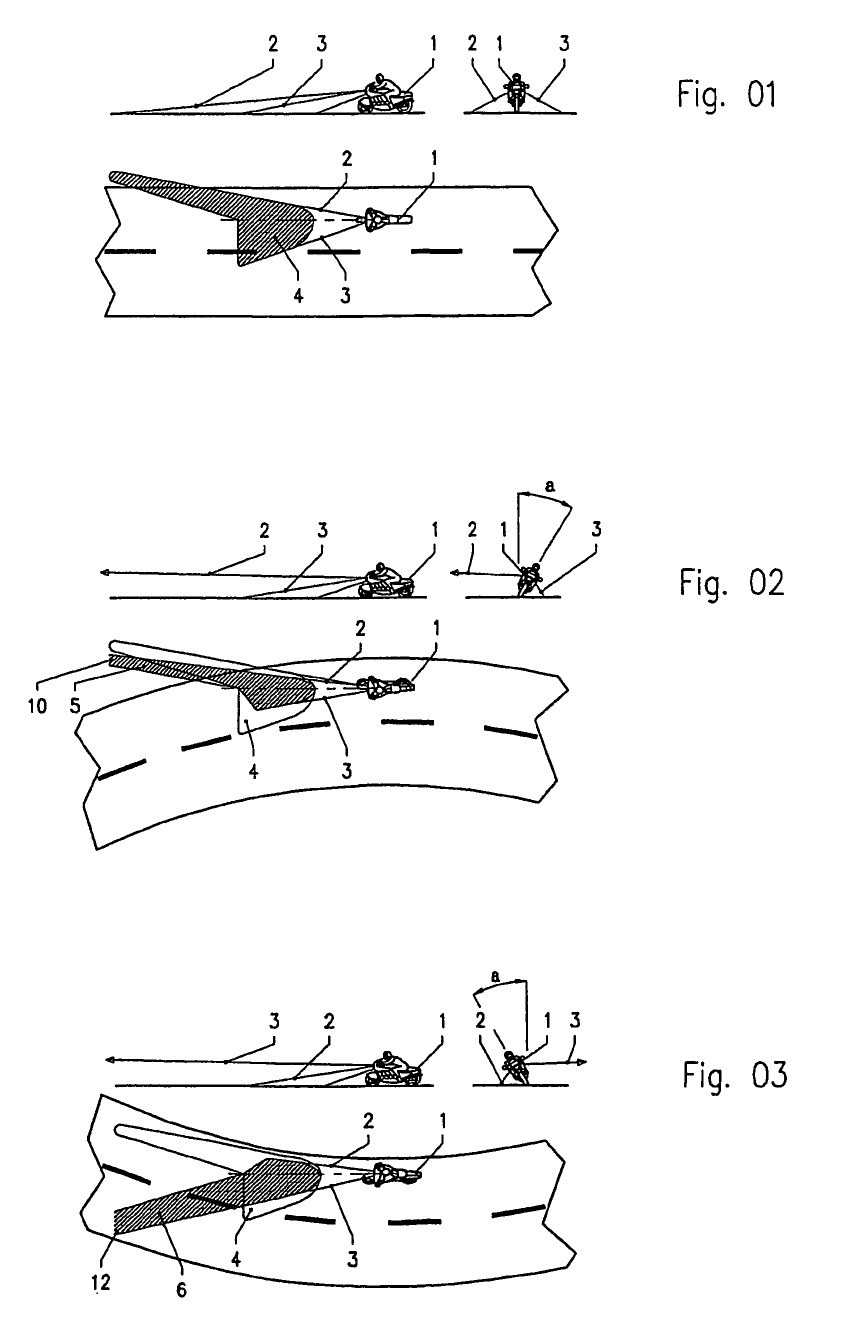
[0011] By means of the inventive headlight unit there is achieved significantly improved illumination during negotiation of a curve, not only in the stretch of driving lane immediately ahead of the vehicle but also on the inside of the respective curve. A particular additional
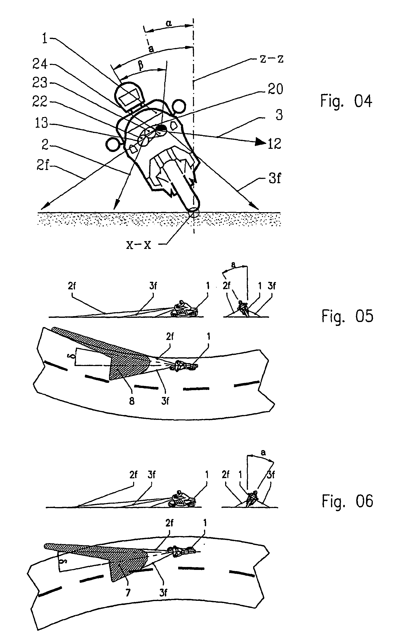
advantage is prevention of the blinding effect, not only because only one of the lateral headlights or only the headlights on one side relative to the central headlight are turned on during negotiation of a curve, while the headlights on the opposite side as well as the middle headlight are turned off, but also—and in particular—because the lateral headlight or lateral headlights are mounted in such a way that they are turned around their
optical axis, thus causing them to be out of
horizontal orientation and, in fact, to be directed toward the inside of the respective curve. Thereby the headlight cone on both sides of the vehicle is directed toward the surface of the driving lane while the said vehicle is inclined during negotiation of a curve, thus substantially maintaining the intended light-
beam pattern. This is of particular importance during driving with dipped low beam, because thereby the elongated lateral light
branch on the right side remains substantially unchanged, while the blinding effect on the left side—which is otherwise unavoidable with the use of a standard headlight, which shines upward because of the greatly inclined orientation of the vehicle—is prevented.
[0018] In this connection, the vertical-axis sensor is used to improve the accuracy of measurement of the degree of lean of the vehicle; it contributes to improvement of the operating safety to the extent that its measured values are analyzed in a computer of the
control unit as part of a plausibility test, in which the degree of lean determined by the longitudinal-axis sensor is compared with the variation of vehicle movement during negotiation of a curve. As explained, the said computer analyzes the signals of both sensors and determines therefrom the transition between driving in substantially upright orientation and negotiation of a curve, by comparing the respective inclination of the vehicle with the minimum roll angle. In the process, the sensor signals are corrected by filtering,
linearization and temperature compensation. The switching instants calculated at the beginning and end of negotiation of a curve are appropriately converted to switching processes of a power circuit for actuation of the headlights.
[0020] By the fact that the inventive headlight unit is composed of individual commercially available headlights, low
system costs are achieved. With the exception of the incandescent lamps themselves, the inventive headlight unit is able to operate without wearing parts, thus also contributing to a concomitant increase in its
functional safety and useful life. By the fact that the blinding effect is largely prevented, it is also possible to use headlights with greater light outputs. The inventive headlight unit can be provided as a retrofit kit, to be mounted in place of a conventional headlight, on the cable connection thereof.
