Flow control system for a gas turbine engine
- Summary
- Abstract
- Description
- Claims
- Application Information
AI Technical Summary
Benefits of technology
Problems solved by technology
Method used
Image
Examples
Embodiment Construction
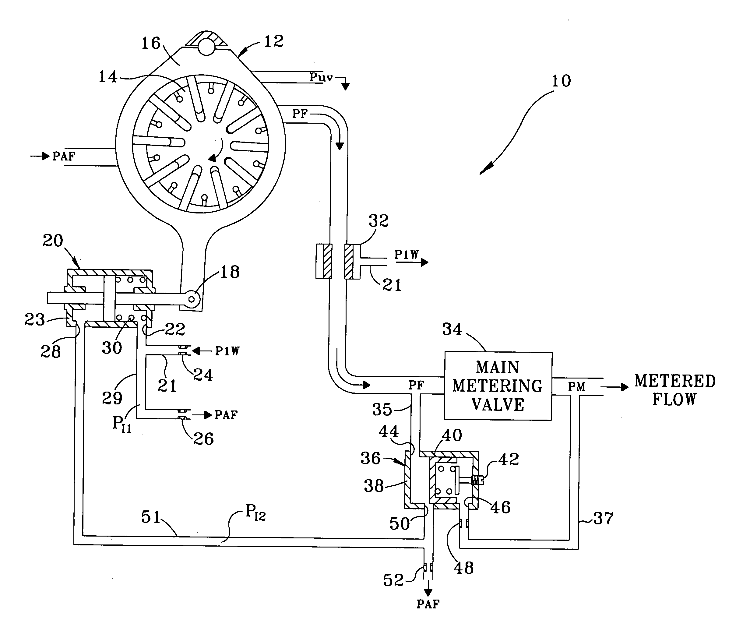
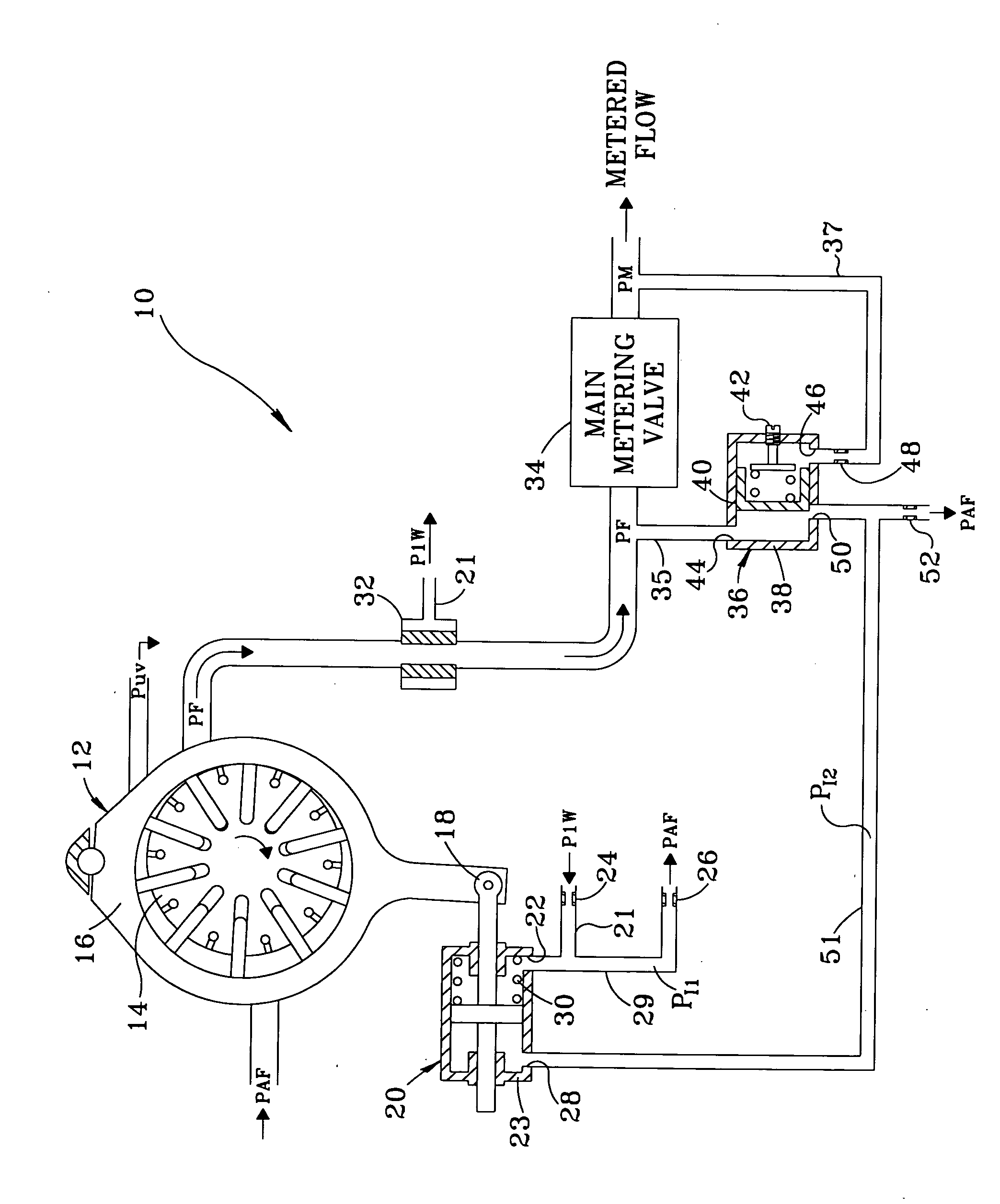
[0014] Referring now to the Sole FIGURE, there is illustrated a schematic representation of a flow control system in accordance with the subject invention which is designated generally by reference numeral 10. For clarity throughout the following description, arrows are shown within the lines of system 10 to indicate the direction in which the fuel flows and an annotated letter “P” is shown to indicate a pressure at certain locations. All relative descriptions herein such as left, right, up, and down are with reference to the system 10 as shown in the Sole FIGURE and not meant in a limiting sense. Additionally, for clarity common items such as filters and shut off solenoids have not been included in the Sole FIGURE. The system 10 maintains the output flow of a variable vane displacement pump 12 to provide fast response to engine needs in a stable manner yet excessive complexity is avoided.
[0015] The pump12 includes a rotor 14 and a pivoting cam ring 16. For a detailed description o...
PUM
 Abstract
Description
Claims
Application Information
 - R&D
- Intellectual Property
- Life Sciences
- Materials
- Tech Scout
- Unparalleled Data Quality
- Higher Quality Content
- 60% Fewer Hallucinations
Browse by: Latest US Patents, China's latest patents, Technical Efficacy Thesaurus, Application Domain, Technology Topic, Popular Technical Reports.
© 2025 PatSnap. All rights reserved.Legal|Privacy policy|Modern Slavery Act Transparency Statement|Sitemap|About US| Contact US: help@patsnap.com


