

Burner
- Summary
- Abstract
- Description
- Claims
- Application Information
AI Technical Summary
Benefits of technology
Problems solved by technology
Method used
Image

Examples
Embodiment Construction
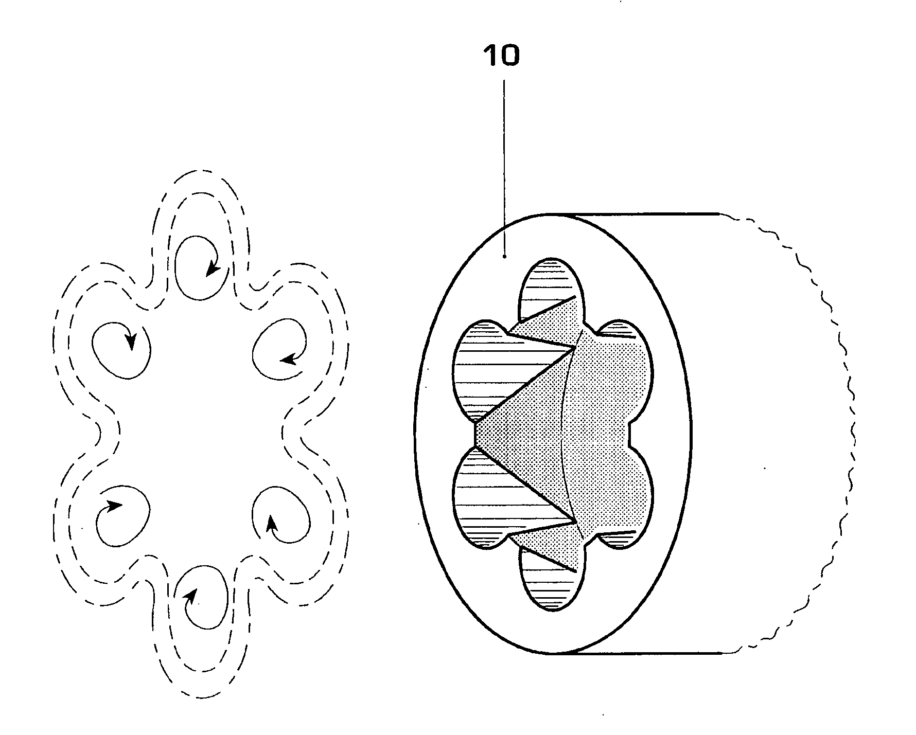
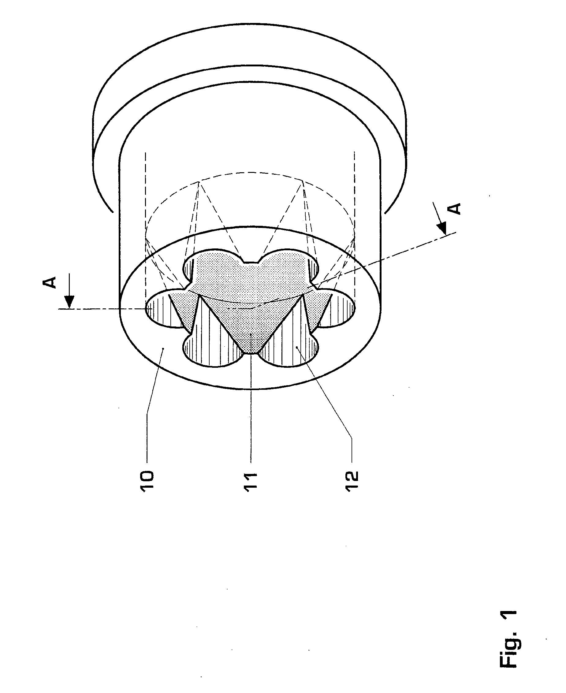
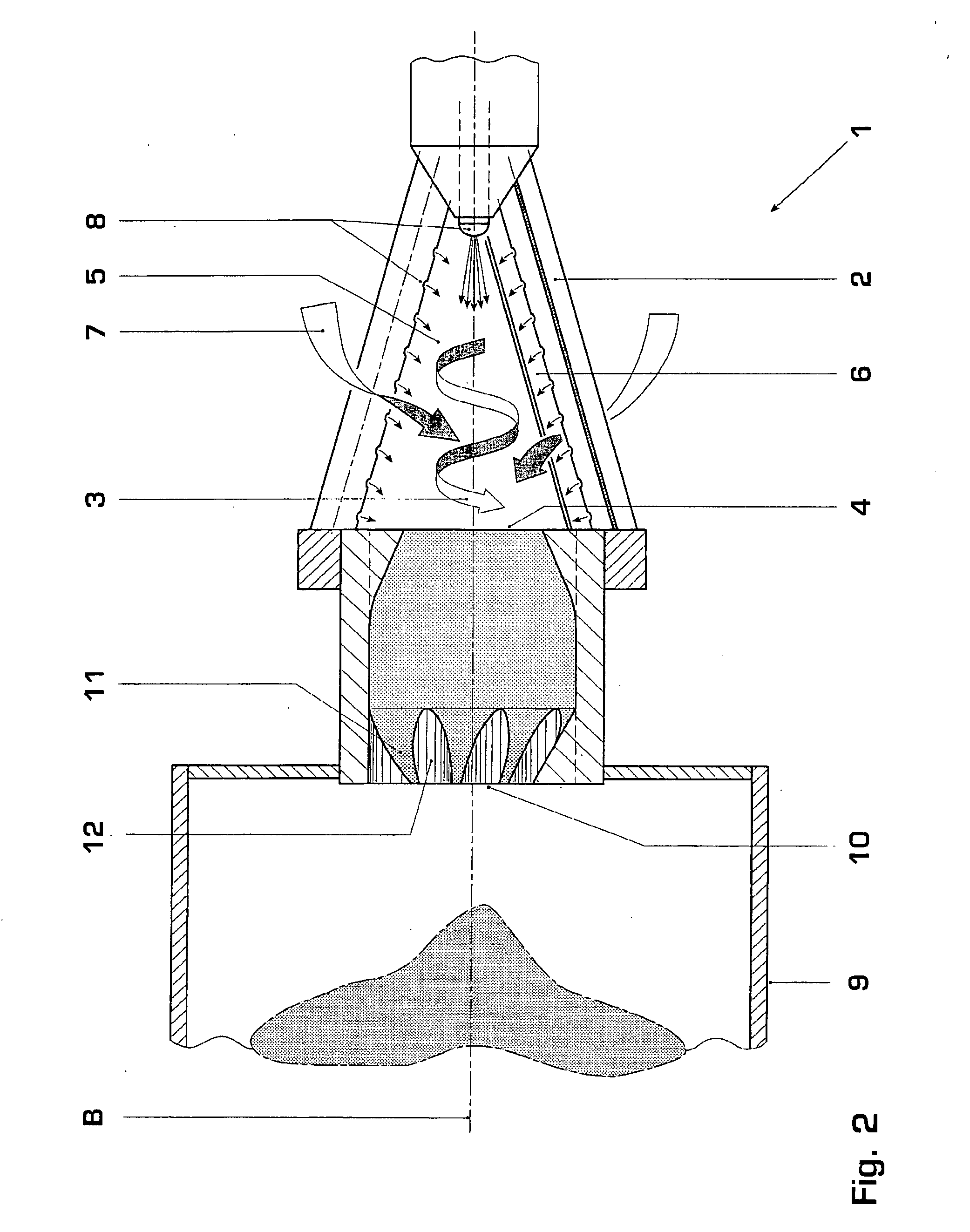
[0022] In FIG. 1, a heat generator has a burner 1 with a swirl generator 2. The swirl generator 2 generates a swirl 3 with an axial flow component facing toward a downstream burner outlet 4. Mixing takes place in an area 5 of the generator 2, so as to ensure adequate mixing of fuel and combustion air. The axial flow cross-section of the area 5 widens in the direction of the outlet 4; this configuration facilitates attainment of a constant swirl 3 in the area 5 with an increasing combustion air mass flow in the direction of the longitudinal axis B of the burner 1. The generator 2 comprises two hollow partial cones (not shown) arranged offset to one another. The offset of the respective centre axes of the partial conical bodies creates two tangential air channels 6. A combustion air flow 7 flows, with a relatively high tangential velocity component, through the two tangential channels 6 into the area 5, thus generating the swirl 3. Fuel is introduced into the burner 1 via a fuel inlet...
PUM
 Abstract
Description
Claims
Application Information