Connector for memory card

a technology for connecting devices and memory cards, applied in the direction of coupling device connections, engagement/disengagement of coupling parts, instruments, etc., can solve the problems of the connector for memory cards becomes tough with respect to static electricity and external noise, and the deformation and abrasion of the housing rarely occur, etc., to achieve the effect of sufficient mechanical strength, easy grounding, and low cos

Inactive Publication Date: 2005-05-12
MATSUSHITA ELECTRIC WORKS LTD
View PDF3 Cites 18 Cited by
  • Summary
  • Abstract
  • Description
  • Claims
  • Application Information

AI Technical Summary

Benefits of technology

[0007] An object of the present invention is to provide a connector for memory card which has a low-profile and a high mechanical strength so that there is no trouble for inserting and drawing the memory card.
[0009] Since the housing is made of metal plate, it has a sufficient mechanical strength even when the housing is formed low-profile. Furthermore, deformation and abrasion of the housing rarely occur when the memory card is repeatedly inserted and drawn. Still furthermore, the housing is easily grounded, so that the connector for memory card becomes tough with respect to the static electricity and the external noise.

Problems solved by technology

Furthermore, deformation and abrasion of the housing rarely occur when the memory card is repeatedly inserted and drawn.
Still furthermore, the housing is easily grounded, so that the connector for memory card becomes tough with respect to the static electricity and the external noise.

Method used


Image

  • Connector for memory card
  • Connector for memory card
  • Connector for memory card

Examples


first embodiment

[0116] A first embodiment of the present invention is described with reference to the drawings.

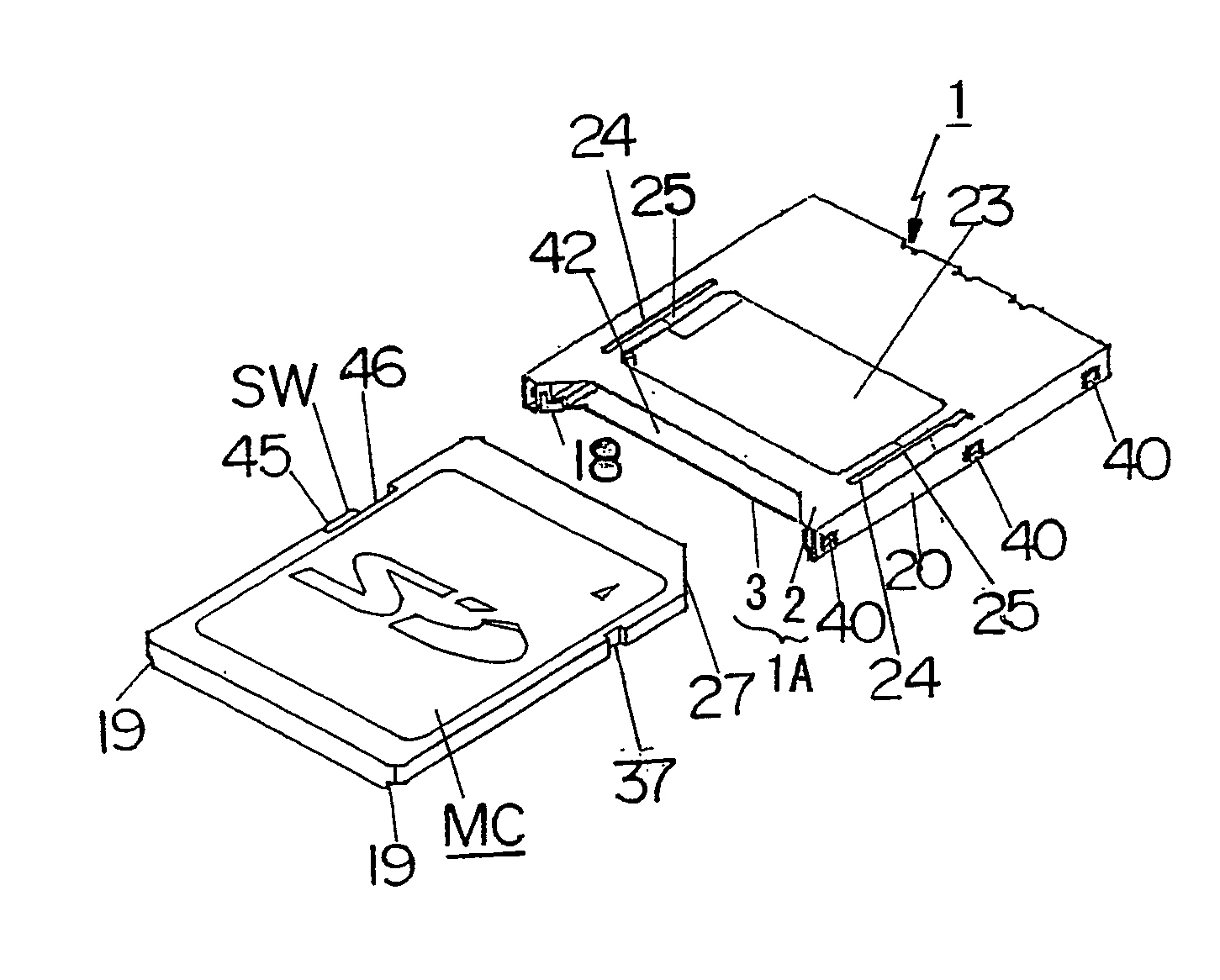
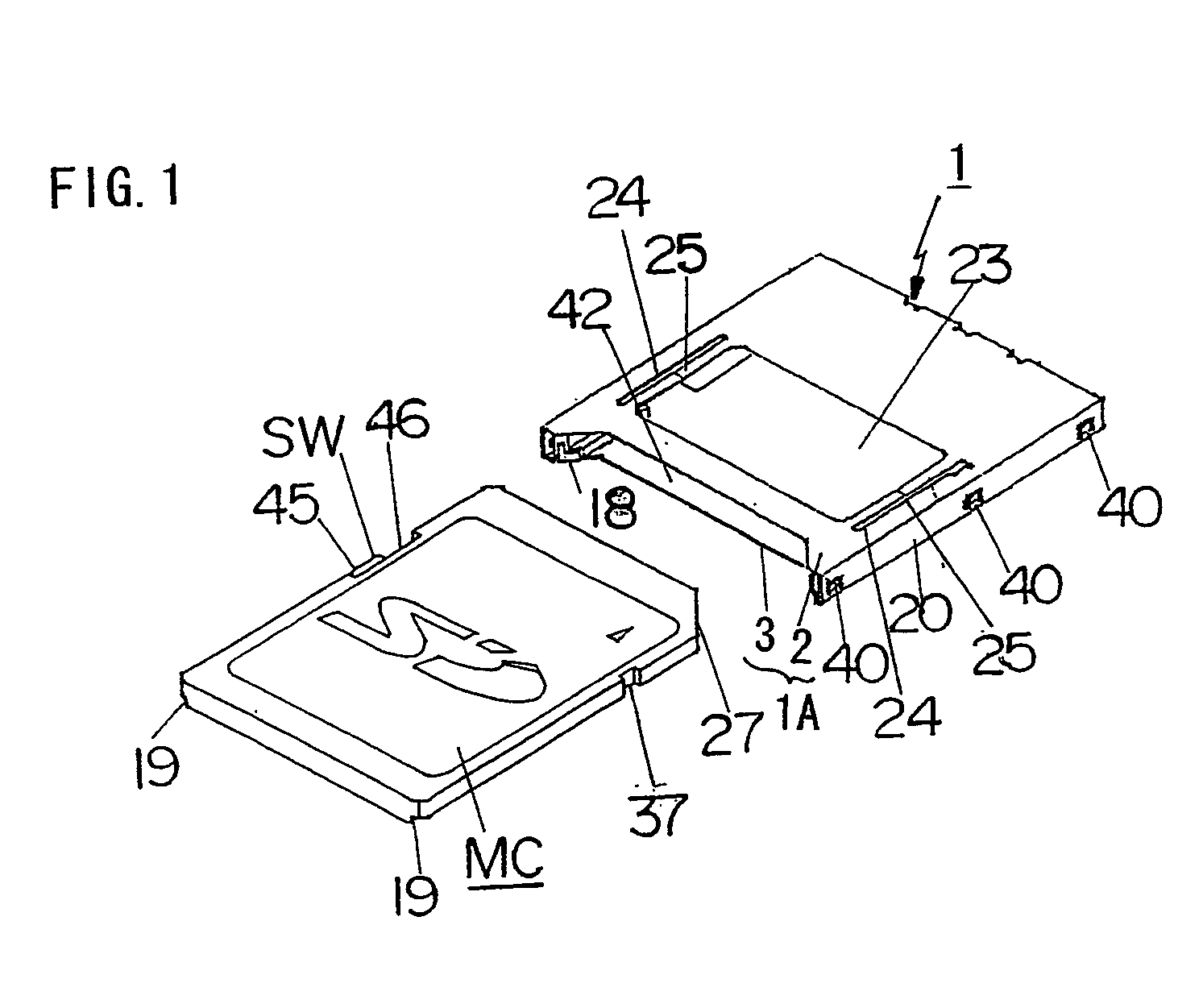
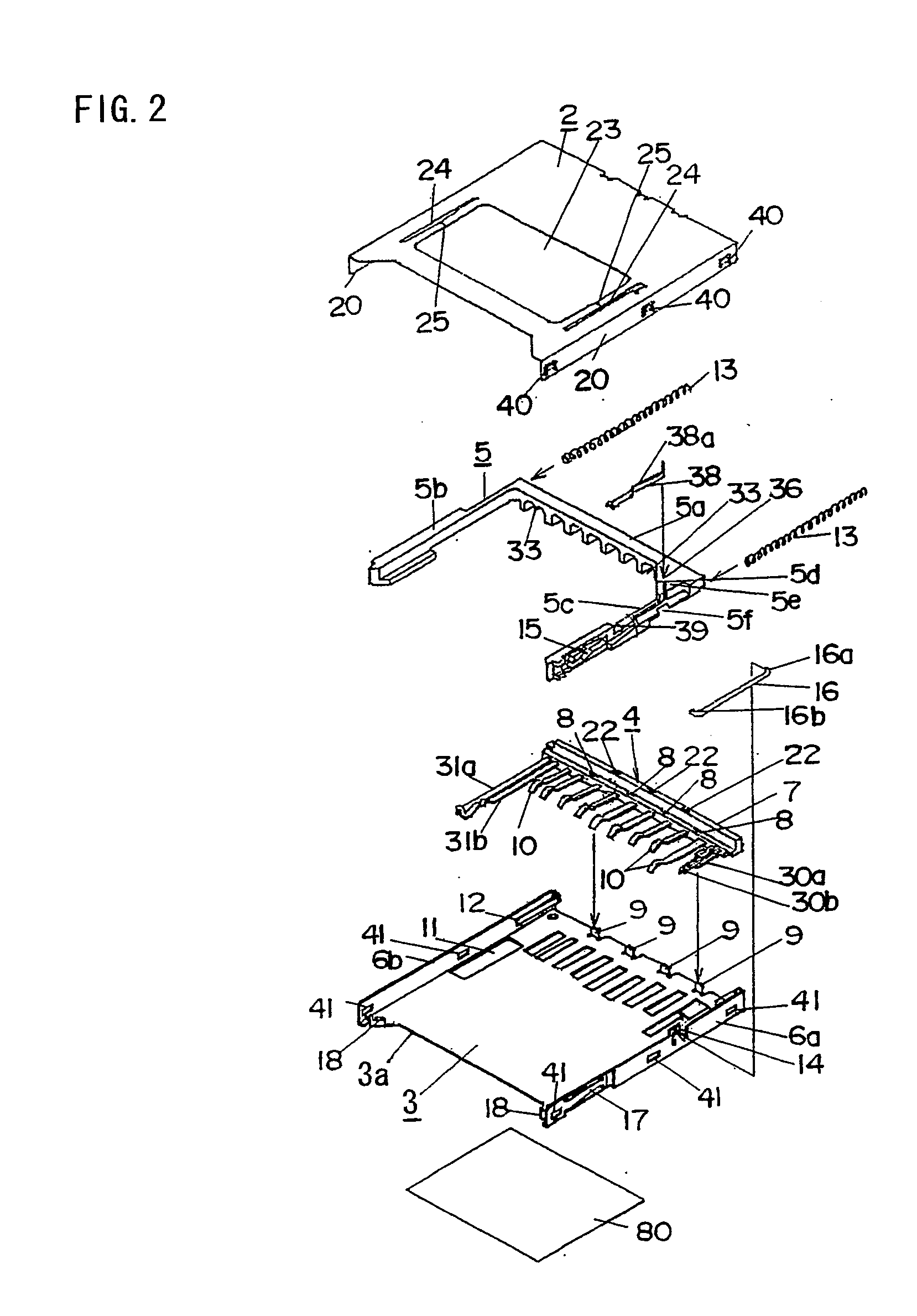
[0117]FIG. 1 shows appearances of a memory card such as an SD card designated by a symbol “MC” and a connecter 1 in the first embodiment. FIG. 2 shows a configuration of the connector 1.

[0118] As can be seen from FIGS. 1 and 2, a planiform housing 1A of the connector 1 is configured by a cover shell 2 and a base shell 3, and the housing 1A has an opening 42 formed on a front face through which the memory card MC is inserted into the housing 1A. The cover shell 2 is formed by punching a thin stainless steel plate to a predetermined shape, and bending the punched plate (blank). Similarly, the base shell 3 is formed by punching a thin stainless steel plate to a predetermined shape, and bending the punched plate (blank). The housing 1A is assembled by engaging the cover shell 2 with the base shell 3. A contact block 4 is provided at a position in the vicinity of a rear end in the housing 1A....

second embodiment

[0177] A second embodiment of the present invention is described. The connector 1 in the first embodiment is on condition that the base shell 3 is fixed on the circuit substrate. Alternatively, in the second embodiment, the cover shell 2 is to be fixed on the circuit substrate. The connector 1 in the second embodiment is called reverse type.

[0178] Details of the reverse type base shell 3 in the second embodiment are shown in FIGS. 14A to 14D. FIG. 14A shows a rear view of the base shell 3. FIG. 14B shows a plan view of the base shell 3. FIG. 14C shows a front view of the base shell 3. FIG. 14D shows a side view of the base shell 3.

[0179] In comparison with FIGS. 3A to 3D in the first embodiment, it is found that the soldering portions 61 are upwardly bent on the front end of the base shell 3. The height of the soldering portions 61 is a little higher than the thickness of the housing 1A in a manner so that the soldering portions 61 is positioned above the outer face of the top pla...

third embodiment

[0186] A third embodiment of the present invention is described. In the description of the third embodiment, the elements which are substantially the same as those in the first embodiment are not referred, and the characteristic elements in the third embodiment are mainly described.

[0187]FIG. 19 shows a configuration of the connector 1 in the third embodiment. In comparison with FIG. 2 in the first embodiment, a pair of spring guide members 100 are independently formed from the base shell 3. The coil springs 13 are fitted into the cuttings 47 formed on the both sides of the base member 7 of the contact block 4 and the grooves 35a and 35b formed on the arms 5b and 5c of the slider 5 from openings on the rear face of the housing 1A. Subsequently, the spring guide members 100 are engaged with the housing 1A in a manner so that spring guide rods 101 of the spring guide members 100 are fitted into the inner hollows of the coil springs 13. Cuttings 110 are formed on the rear end portion ...


PUM


Abstract

In a connector used for connecting a memory card to an apparatus which processes the data memorized in the memory card, a cover shell and a base shell which configure a box-shaped housing are respectively formed by a metal thin plate for increasing the mechanical strength of the hosing and easily for grounding the housing so that the connector can be tough with respect to the static electricity and the external noise. Contacts which are to be contacted with contacts of a memory card are integrally held on a contact base formed by insert molding so that contacting portions of and soldering terminals of the contacts can be aligned parallel to and on the same level as each other. A slider moving forward and backward in the housing corresponding to the insertion and drawing of the memory card are pressed by pressing forces of a pair of coil springs so that the movement of the slider can be made smooth.

Description

FIELD OF THE INVENTION [0001] The present invention relates to a connector used for connecting a memory card such as an SD (Secure Digital) card detachably to an apparatus processing the data memorized in the memory card. BACKGROUND OF THE INVENTION [0002]FIG. 43 shows a configuration of a conventional connector for connecting the memory card such as the SD card. The conventional connector comprises a cover shell 1000 made of a thin metal plate, a base member 1001 made of a resin molding, a slider 1002 made of a resin molding, a coil spring 1003 for pushing the slider 1002 forward, a plurality of contacts 1004, switching pieces 1005a and 1005b for sensing whether writing protection is switched on or off, a rod 1006 having a hook at an end thereof which is engaged with a heart cam groove 1007 formed on a side face of the slider 1002, and engaging members 1008 which are engaged with front ends on both sides of the base member 1001 for fixing the cover shell 1000 on the base member 100...

Claims


Application Information

Patent Timeline
Patent Type & Authority Applications(United States)
IPC IPC(8): G06K17/00G06K7/00H01R13/629H01R13/703H01R43/00
CPCG06K7/0021H01R12/71
Inventor TANAKA, HIROHISATAKEYAMA, HIDETOSHI
Owner MATSUSHITA ELECTRIC WORKS LTD
Why Eureka
Try Eureka