
Method and system for frequency offset estimation

a frequency offset and estimation technology, applied in the direction of modulated carrier systems, transmission, angle demodulation, etc., can solve the problems of complex implementation, loss of information or performance, affecting the reception performance of msr,

Inactive Publication Date: 2005-05-12
ST ERICSSON SA
View PDF2 Cites 7 Cited by
  • Summary
  • Abstract
  • Description
  • Claims
  • Application Information

AI Technical Summary

Benefits of technology

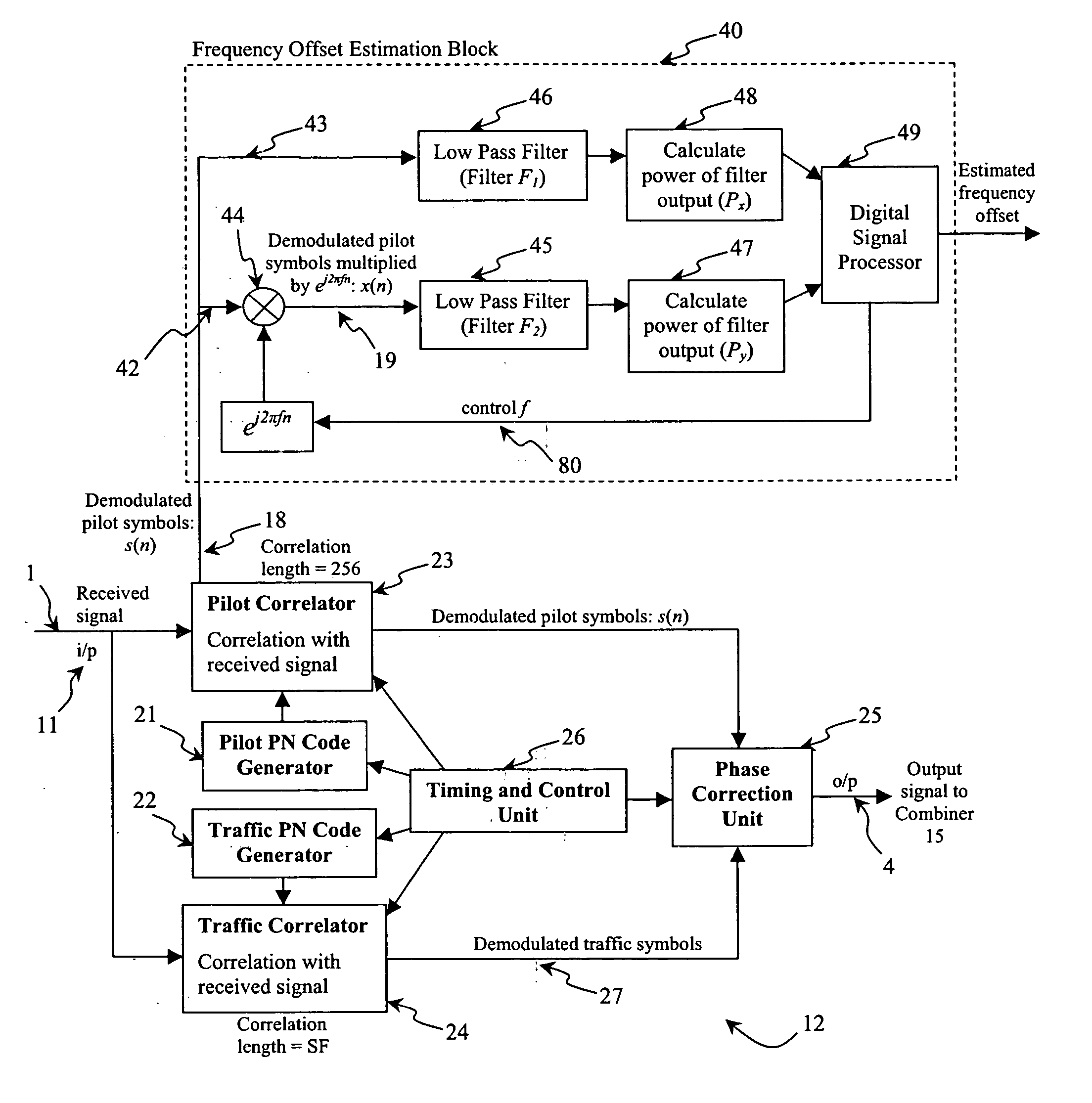
[0017] In an embodiment, (e) includes: performing a comparison of the power of said filtered first signal with the power of said filtered second signal, and if said comparison indicates that a first predetermined condition is not satisfied, performing a first adjustment of said frequency factor and repeating (b) to (d). If said comparison indicates that the first predetermined condition is satisfied, the method includes performing a second adjustment of said frequency factor. The comparison includes determining whether the power of said filtered second signal is less than the power of said filtered first signal multiplied by a predetermined correction factor. The first adjustment of said frequency factor comprises increasing said frequency factor. The second adjustment includes subtracting a predefined control factor, X, from said frequency factor. The method further includes performing a comparison of the control factor, X, with a predetermined accuracy level, wherein if the comparison indicates that a second predetermined condition is not satisfied, said first adjustment is performed. The first adjustment includes assigning a new value of X/2 to said control value, and adding the new control factor to said frequency factor before repeating (b) to (d).
[0018] The comparison of the control factor with the predetermined accuracy level is represented by X=2−a, where a is a predeter

Problems solved by technology

If those two signals were received and combined by the MSR in anti-phase (or 180° in phase apart) then those two signals will cancel each other out, which thus leads to loss of information or performance.
It is desirable for the MSR to estimate, and compensate for, this frequency offset since without such correction, degradation of the signal will result and thus affect the MSR's reception performance.
This technique requires division, which is complex to implement.
Also, the output of the inverse tangent function can only be calculated to approximation (by using Taylor series or lookup tables) which inevitably results in errors or imprecision.

Method used


Image

  • Method and system for frequency offset estimation
  • Method and system for frequency offset estimation
  • Method and system for frequency offset estimation

Examples


Embodiment Construction

[0042] Embodiments of a method and system for frequency offset estimation are described herein. In the following description, numerous specific details are given to provide a thorough understanding of embodiments. One skilled in the relevant art will recognize, however, that the invention can be practiced without one or more of the specific details, or with other methods, components, materials, etc. In other instances, well-known structures, materials, or operations are not shown or described in detail to avoid obscuring aspects of the invention.

[0043] Reference throughout this specification to “one embodiment” or “an embodiment” means that a particular feature, structure, or characteristic described in connection with the embodiment is included in at least one embodiment. Thus, the appearances of the phrases “in one embodiment” or “in an embodiment” in various places throughout this specification are not necessarily all referring to the same embodiment. Furthermore, the particular...


PUM


Abstract

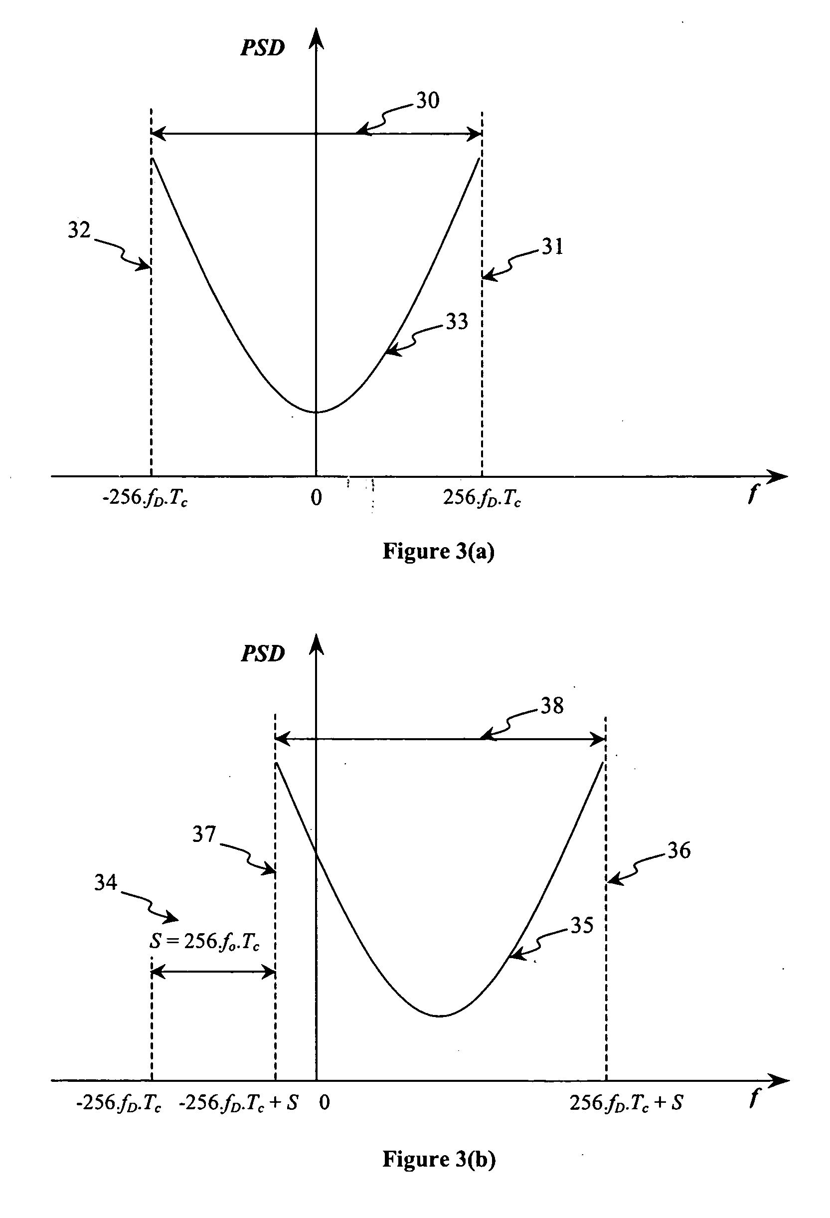
A method and system for estimating a frequency offset between a receiver and a transmitter, including the steps of, or means for: (a) receiving a first signal from said transmitter and demodulating the first signal; (b) performing a frequency shift on said first signal by a predetermined frequency factor to generate a second signal; (c) filtering each of said first and second signals; (d) determining the power of each of the filtered first and second signals; (e) determining an upper corner frequency value of the first signal using the power of the filtered first and second signals; (f) determining a lower corner frequency of the first signal using the determined power of the filtered first and second signals; and (g) determining a frequency offset value based on said upper corner frequency value and said lower corner frequency value.

Description

BACKGROUND OF THE INVENTION [0001] 1. Field of the Invention [0002] The present disclosure generally relates to a method and system for estimating the relative frequency offset between a Base Station Transmitter and Mobile Station Receiver for a wireless communications system, and in particular but not exclusively, for a Wideband Code Division Multiple Access (“W-CDMA”) radio telecommunications system. [0003] 2. Description of the Related Art [0004] In a radio communications system, signals are typically transmitted from the fixed location of a Base Station (“BS”) (such as a radio transmission tower) and travel towards a moveable Mobile Station Receiver (“MSR”) (such as a mobile phone) via many different physical paths. The signal received by the MSR will rarely be in exactly the same form as the original transmitted signal, due to influences from the physical environment during propagation. Along each propagation path, the signal may be subjected to interference from background noi...

Claims


Application Information

Patent Timeline
IPC IPC(8): H04B1/707H04L27/00
CPCH04B1/7087H04B1/7115H04L2027/0091H04L2027/0046H04L2027/0065H04L2027/0024
Inventor MURALIDHAR, KARTHIKOH, SER WAH
Owner ST ERICSSON SA
Learn More